Operation – Tri Tool 602-5SBM Clamshell Air User Manual
Page 20
20
TRI TOOL INC.
92-0093 Rev. 131230
OPERATION
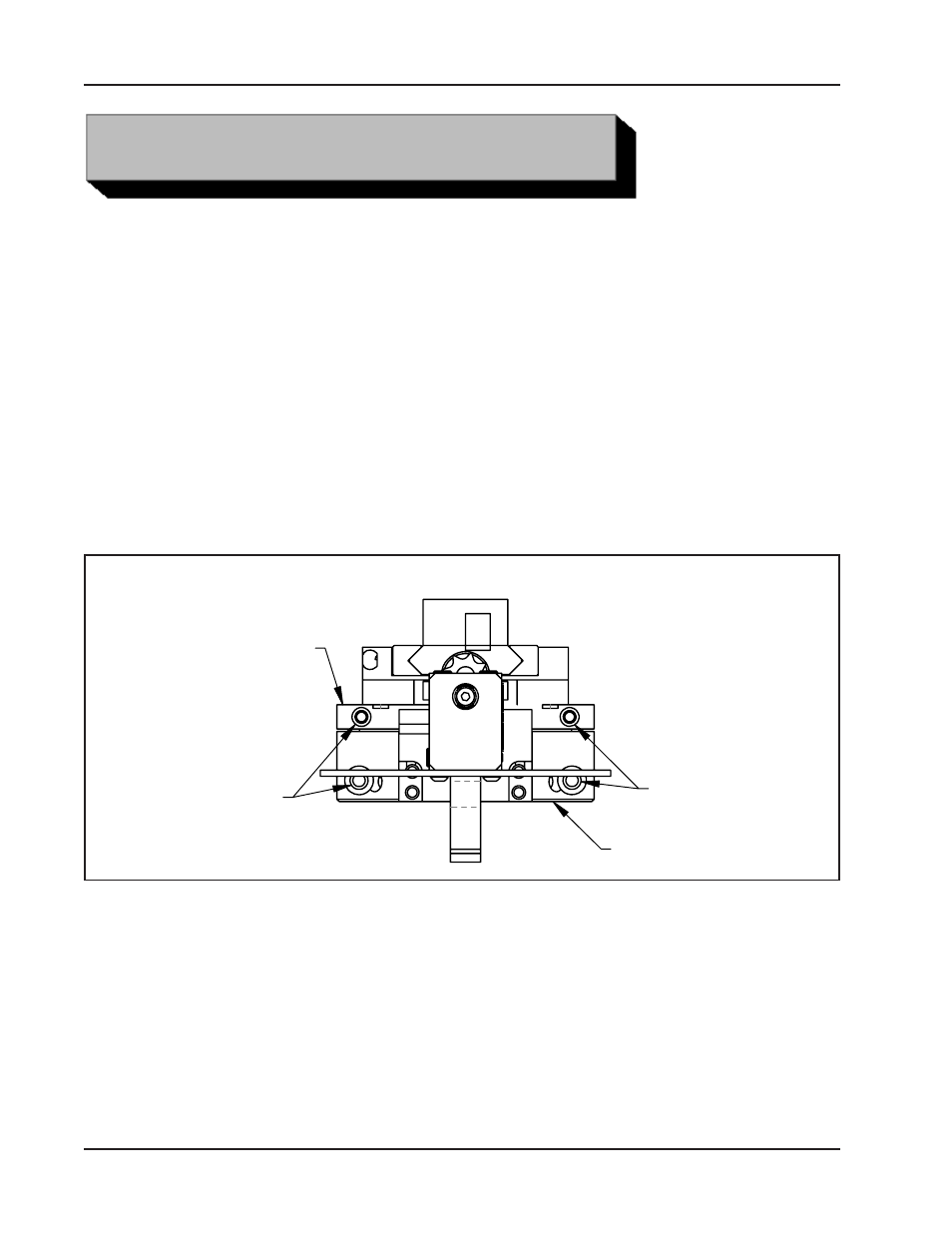
Locking Screw Locations
Read the operation instructions carefully before attempting to operate the Model
602.5SBM Low Profile Clamshell.
See ‘Configure the Clamshell for the specific task required’ later in this section to
configure the machine.
Do not install the Tool Bits until the Clamshell is installed on the pipe.
INSTALLATION OF THE CLAMSHELL ON AN IN-LINE PIPE
Separate the two halves of the Clamshell.
Disengage the Air Motor by removing the Motor Hold-down Bolt and removing the
Air Motor from the drive socket.
LOCKING
SCREWS
HOUSING
LOCKING
SCREWS
HEADSTOCK
By hand, rotate the Headstock until the split-lines of the Headstock match the
split-line of the Housing.
Unbolt the two halves of the Clamshell.
Two Locking Screws are located on the Housing and two more on the Headstock.
These Locking Screws are captured in their holes so that they will not come totally
free of the Clamshell. Refer to “Locking Screw locations”.