Watson-Marlow Bredel 265 User Manual
Page 54
Advertising
MAINTENANCE
54
4.
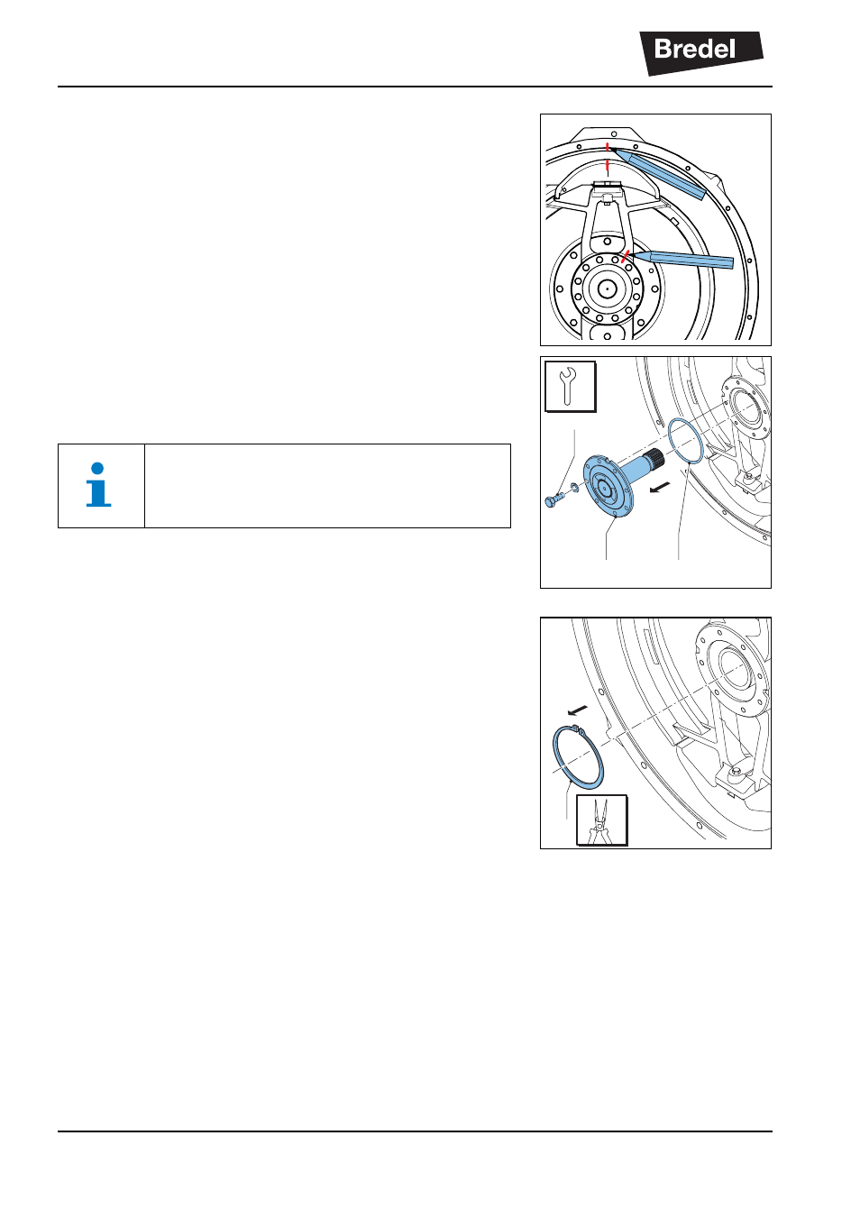
Mark the position of the drive shaft in relation to
the rotor before removing the drive shaft. Also,
mark the position of the rotor in relation to the
pump house before removing the retaining
bolts. This will ensure that the angle between
the two rotors will be 90 degrees.
5.
Remove the retaining bolts (A) of the drive shaft
(B) and remove the drive shaft. Check the
sealing ring (C) for damage.
6.
Remove the rotor retaining circlip (A), which
locks the rotor on the hub. Use the correct tools
to do this.
B
A
C
If the drive shaft cannot be removed manu-
ally, use a screwdriver in the slots in the
rotor provided for this purpose.
A
Advertising
This manual is related to the following products: