Watson-Marlow Bredel 265 User Manual
Page 66
MAINTENANCE
66
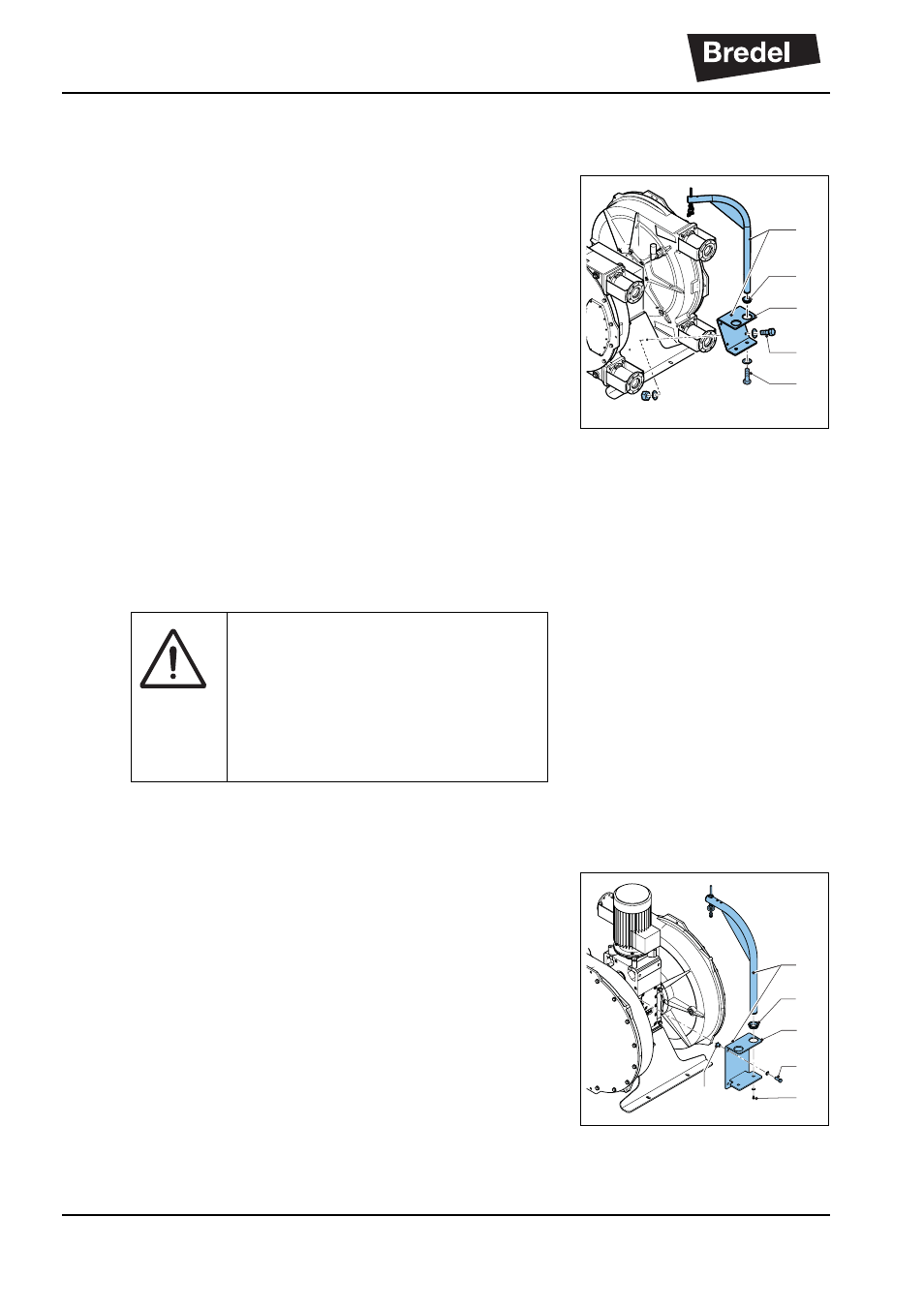
8.9.4
Installing the cover lifting device (CLD) on a
horizontal configuration
1.
Define the position.
The cover lifting device (CLD) must be mounted
on the frame on the opposite position of the
motor side. See the illustration.
2.
Fit the bracket.
Fit the bracket (A) with the supplied fasteners
(B) on the frame of the unit.
The torque on the bolts should be 210 Nm
(1858.7 lbs in.).
3.
Insert the lifting pole.
The lifting pole (C) is fastened on the bottom
side of the bracket with a bolt (D). Furthermore,
the lifting pole is supported by a ring (E), which
is placed in the hole of the bracket.
8.9.5
Installing the cover lifting device (CLD) on a
vertical configuration
1.
Define the position
The cover lifting device (CLD) must be mounted
with the help of a female threaded bush on the
gear reducer. This can be done on both sides of
the gear reducer. See the illustration.
2.
Fit the bracket
Fit the bracket (A) with the supplied fasteners
(B) and female threaded bush (F) on the gear
reducer. The bush should be placed in the
spacing of the gear reducer used for attaching
the gear reducer to a frame or support.
A
B
E
C
D
WARNING
Do not exceed the maximum
allowed lifting weight of 200 kg/
440 lbs during the lifting of the
cover. This is also indicated on the
CLD.
A
B
E
C
D
F