Switch 5 (line modulation), Led status indicators – Westermo TD-32 User Manual
Page 13
13
6178-2203
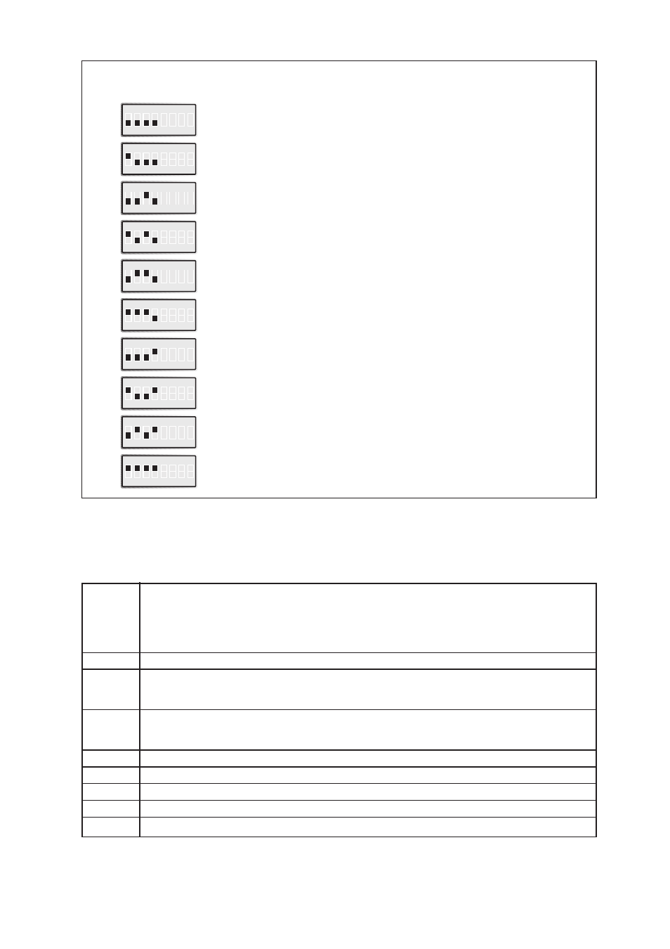
Switch 5 (line modulation)
Used saved parameters
(ATF1)
V.21; 300
bit/s
(ATF4)
V.22; 1 200 bit/s
(ATF5)
V.22bis; 2 400
bit/s
(ATF6)
V.32bis; 4 800
bit/s
Related
AT-commands
ON
1 2 3 4 5 6 7 8
ON
1 2 3 4 5 6 7 8
ON
1 2 3 4 5 6 7 8
(ATF7)
V.32bis; 7 200
bit/s
ON
1 2 3 4 5 6 7 8
(ATF8)
V.32bis; 9 600
bit/s
ON
1 2 3 4 5 6 7 8
(ATF9)
V.32bis; 12 000 bit/s
ON
1 2 3 4 5 6 7 8
(ATF10)
V.32bis; 14 400 bit/s
ON
1 2 3 4 5 6 7 8
(ATF0)
Auto detect mode
ON
1 2 3 4 5 6 7 8
ON
1 2 3 4 5 6 7 8
ON
1 2 3 4 5 6 7 8
LED Status Indicators
PWR
Full Intensity
The modem is functioning normally
Half intensity
The modem is in test mode
Occasional flashing with speaker click
Power supply problem
1:6, on:off ratio
RAM error
On/off with speaker click
Modem unable to start
LINE
LED lights up when the modem has the line
ANS
LED flashes when a ring is detected on the line. The ANS indicator shines
constantly when answering an incoming call and remains lit thereafter
to indicate the modem is in auto answer mode.
REL
LED flashes when the modem is in both error correcting and compressing mode.
When the modem is only in error correcting mode this LED is on.
When the modem is in direct or normal mode this LED remains off.
TD
Transmitted Data: Displays data received from the local RS-232/V.24 port
RD
Received Data: Displays data leaving the modem on the RS-232/V.24 port
RTS
Request to Send signal from the DTE
DCD
Data Carrier Detect modem signal
DSR
Data Set Ready modem signal
Please also refer to AT&C, AT\N, AT&T, ATS0