Network requirements, Configuration procedure – H3C Technologies H3C S7500E Series Switches User Manual
Page 28
2-7
<Switch> system-view
[Switch] interface vlan-interface 10
[Switch-Vlan-interface10] local-proxy-arp enable
The ping operation from Host A to Host B is successful after the configuration.
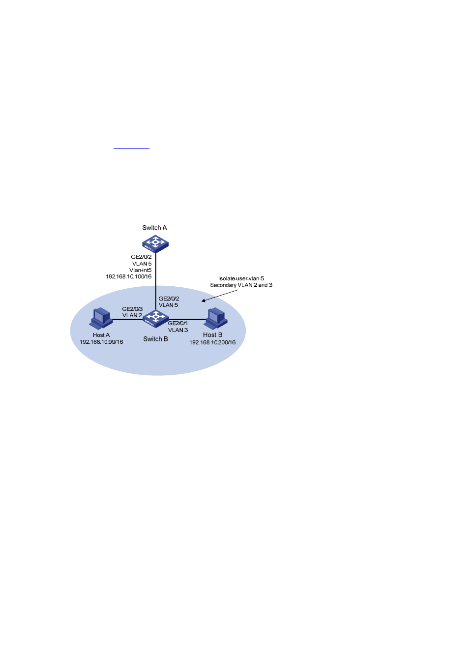
Local Proxy ARP Configuration Example in Isolate-User-VLAN
Network requirements
As shown in
, Switch B is attached to Switch A. VLAN 5 on Switch B is an isolate-user-VLAN,
which includes uplink port GigabitEthernet2/0/2 and two secondary VLANs, VLAN 2 and VLAN 3.
GigabitEthernet2/0/3 belongs to VLAN 2, and GigabitEthernet2/0/1 belongs to VLAN 3.
Configure local proxy ARP on Switch A to implement Layer 3 communication between VLAN 2 and
VLAN 3.
Figure 2-6 Network diagram for local proxy ARP configuration in isolate-user-VLAN
Configuration procedure
1) Configure Switch B
# Create VLAN 2, VLAN 3, and VLAN 5 on Switch B. Add GigabitEthernet2/03 to VLAN 2,
GigabitEthernet2/01 to VLAN 3, and GigabitEthernet2/02 to VLAN 5. Configure VLAN 5 as the
isolate-user-VLAN, and VLAN 2 and VLAN 3 as secondary VLANs. Configure the mappings between
isolate-user-VLAN and the secondary VLANs.
<SwitchB> system-view
[SwitchB] vlan 2
[SwitchB-vlan2] port GigabitEthernet2/03
[SwitchB-vlan2] quit
[SwitchB] vlan 3
[SwitchB-vlan3] port GigabitEthernet2/01
[SwitchB-vlan3] quit
[SwitchB] vlan 5
[SwitchB-vlan5] port GigabitEthernet2/02
[SwitchB-vlan5] isolate-user-vlan enable
[SwitchB-vlan5] quit
[SwitchB] isolate-user-vlan 5 secondary 2 3