Configuration procedure, Network requirements – H3C Technologies H3C S7500E Series Switches User Manual
Page 96
9-6
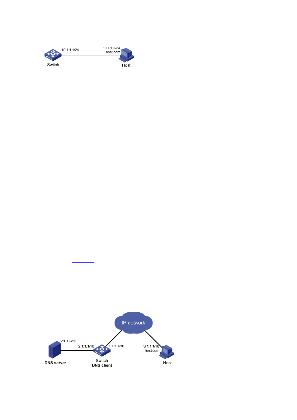
Figure 9-3 Network diagram for static domain name resolution
Configuration procedure
# Configure a mapping between host name host.com and IP address 10.1.1.2.
<Sysname> system-view
[Sysname] ip host host.com 10.1.1.2
# Use the ping host.com command to verify that the Switch can use static domain name resolution to
resolve domain name host.com into IP address 10.1.1.2.
[Sysname] ping host.com
PING host.com (10.1.1.2):
56 data bytes, press CTRL_C to break
Reply from 10.1.1.2: bytes=56 Sequence=1 ttl=128 time=1 ms
Reply from 10.1.1.2: bytes=56 Sequence=2 ttl=128 time=4 ms
Reply from 10.1.1.2: bytes=56 Sequence=3 ttl=128 time=3 ms
Reply from 10.1.1.2: bytes=56 Sequence=4 ttl=128 time=2 ms
Reply from 10.1.1.2: bytes=56 Sequence=5 ttl=128 time=3 ms
--- host.com ping statistics ---
5 packet(s) transmitted
5 packet(s) received
0.00% packet loss
round-trip min/avg/max = 1/2/4 ms
Dynamic Domain Name Resolution Configuration Example
Network requirements
As shown in
, the IP address of the DNS server is 2.1.1.2/16 and the name suffix is com. The
mapping between domain name host and IP address 3.1.1.1/16 is stored in the com domain.
Dynamic domain name resolution and the domain name suffix are configured on the Switch that
serves as a DNS client, and thus the Switch can use domain name host to access the host with the
domain name host.com and the IP address 3.1.1.1/16.
Figure 9-4 Network diagram for dynamic domain name resolution