Dns proxy configuration example, Network requirements – H3C Technologies H3C S7500E Series Switches User Manual
Page 99
9-9
<Sysname> system-view
[Sysname] dns resolve
# Specify the DNS server 2.1.1.2.
[Sysname] dns server 2.1.1.2
# Configure com as the name suffix.
[Sysname] dns domain com
3) Configuration
verification
# Use the ping host command on the Switch to verify that the communication between the Switch and
the host is normal and that the corresponding destination IP address is 3.1.1.1.
[Sysname] ping host
Trying DNS resolve, press CTRL_C to break
Trying DNS server (2.1.1.2)
PING host.com (3.1.1.1):
56 data bytes, press CTRL_C to break
Reply from 3.1.1.1: bytes=56 Sequence=1 ttl=126 time=3 ms
Reply from 3.1.1.1: bytes=56 Sequence=2 ttl=126 time=1 ms
Reply from 3.1.1.1: bytes=56 Sequence=3 ttl=126 time=1 ms
Reply from 3.1.1.1: bytes=56 Sequence=4 ttl=126 time=1 ms
Reply from 3.1.1.1: bytes=56 Sequence=5 ttl=126 time=1 ms
--- host.com ping statistics ---
5 packet(s) transmitted
5 packet(s) received
0.00% packet loss
round-trip min/avg/max = 1/1/3 ms
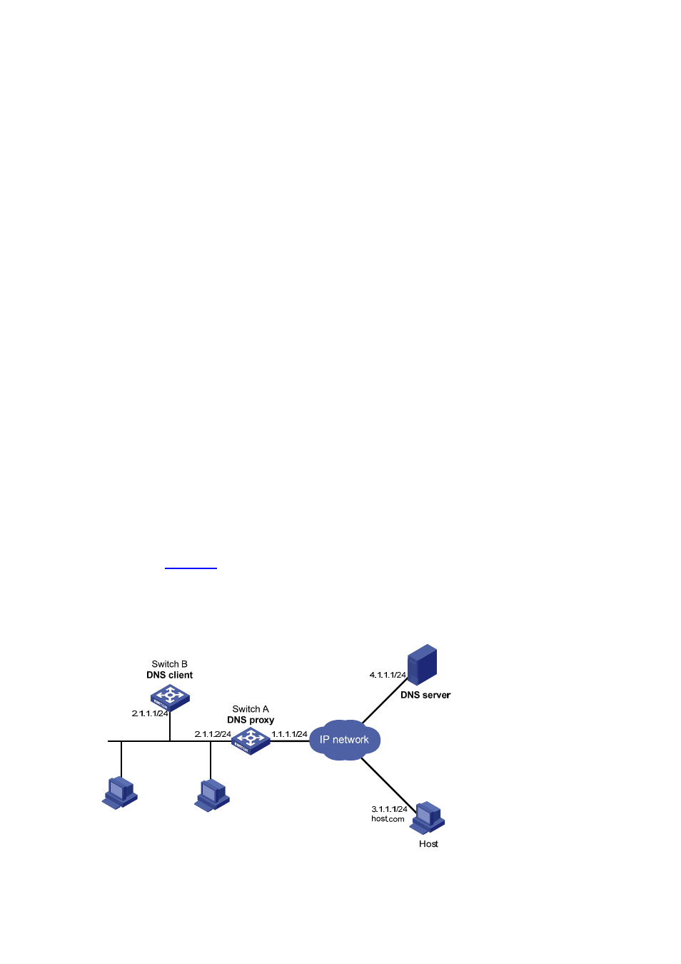
DNS Proxy Configuration Example
Network requirements
As shown in
, specify Switch A as the DNS server of Switch B (the DNS client). Switch A acts
as a DNS proxy. The IP address of the real DNS server is 4.1.1.1.
Switch B implements domain name resolution through Switch A.
Figure 9-8 Network diagram for DNS proxy