Self-defined option configuration example, Network requirements, Configuration procedure – H3C Technologies H3C S7500E Series Switches User Manual
Page 64
5-21
[SwitchA-dhcp-pool-0] quit
# Configure DHCP address pool 1 (address range, gateway, lease duration, and WINS server).
[SwitchA] dhcp server ip-pool 1
[SwitchA-dhcp-pool-1] network 10.1.1.0 mask 255.255.255.128
[SwitchA-dhcp-pool-1] gateway-list 10.1.1.126
[SwitchA-dhcp-pool-1] expired day 10 hour 12
[SwitchA-dhcp-pool-1] nbns-list 10.1.1.4
[SwitchA-dhcp-pool-1] quit
# Configure DHCP address pool 2 (address range, gateway, and lease duration).
[SwitchA] dhcp server ip-pool 2
[SwitchA-dhcp-pool-2] network 10.1.1.128 mask 255.255.255.128
[SwitchA-dhcp-pool-2] expired day 5
[SwitchA-dhcp-pool-2] gateway-list 10.1.1.254
3) Verification
After the preceding configuration is complete, clients on networks 10.1.1.0/25 and 10.1.1.128/25 can
obtain IP addresses on the corresponding network and other network parameters from Switch A. You
can use the display dhcp server ip-in-use command on the DHCP server to view the IP addresses
assigned to the clients.
Self-Defined Option Configuration Example
Network requirements
As shown in
, the DHCP client (Switch B) obtains an IP address and PXE server addresses
from the DHCP server (Switch A). The IP address belongs to network segment 10.1.1.0/24. The PXE
server addresses are 1.2.3.4 and 2.2.2.2.
The DHCP server assigns PXE server addresses to DHCP clients through Option 43, a self-defined
option. The format of Option 43 and that of the PXE server address sub-option are shown in
, respectively. The value of Option 43 configured on the DHCP server in this example is
80 0B 00 00 02 01 02 03 04 02 02 02 02. The number 80 is the value of the sub-option type. The
number 0B is the value of the sub-option length. The numbers 00 00 are the value of the PXE server
type. The number 02 indicates the number of servers. The numbers 01 02 03 04 02 02 02 02 indicate
that the PXE server addresses are 1.2.3.4 and 2.2.2.2.
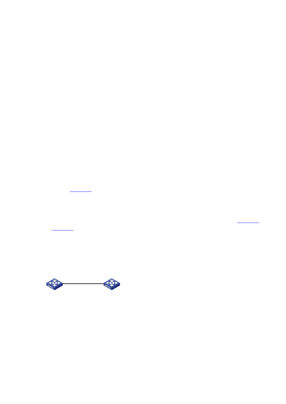
Figure 5-3 Network diagram for self-defined option configuration (a switch as the DHCP server)
Switch A
DHCP server
Switch B
DHCP client
Vlan-int2
10.1.1.1/24
Vlan-int2
Configuration procedure
1) Specify IP addresses for the interfaces (omitted).
2) Configure the DHCP server
# Enable DHCP.
<SwitchA> system-view
[SwitchA] dhcp enable
# Enable the DHCP server on VLAN-interface 2.
[SwitchA] interface vlan-interface 2