Example for upper-layer software referencing acls, Network requirements, Network diagram – H3C Technologies H3C S3100 Series Switches User Manual
Page 572: Configuration procedure
1-15
Example for Upper-Layer Software Referencing ACLs
Example for Controlling Telnet Login Users by Source IP
Network requirements
Apply an ACL to permit users with the source IP address of 10.110.100.52 to telnet to the switch.
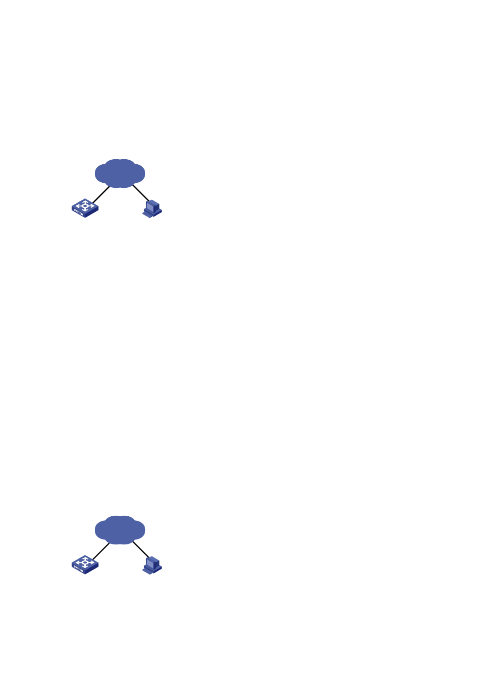
Network diagram
Figure 1-1 Network diagram for controlling Telnet login users by source IP
Switch
PC
10.110.100.52
Internet
Configuration procedure
# Define ACL 2000.
<Sysname> system-view
[Sysname] acl number 2000
[Sysname-acl-basic-2000] rule 1 permit source 10.110.100.52 0
[Sysname-acl-basic-2000] quit
# Reference ACL 2000 on VTY user interface to control Telnet login users.
[Sysname] user-interface vty 0 4
[Sysname-ui-vty0-4] acl 2000 inbound
Example for Controlling Web Login Users by Source IP
Network requirements
Apply an ACL to permit Web users with the source IP address of 10.110.100.46 to log in to the switch
through HTTP.
Network diagram
Figure 1-2 Network diagram for controlling Web login users by source IP
Switch
PC
10.110.100.46
Internet