H3C Technologies H3C MSR 50 User Manual
Page 15
7
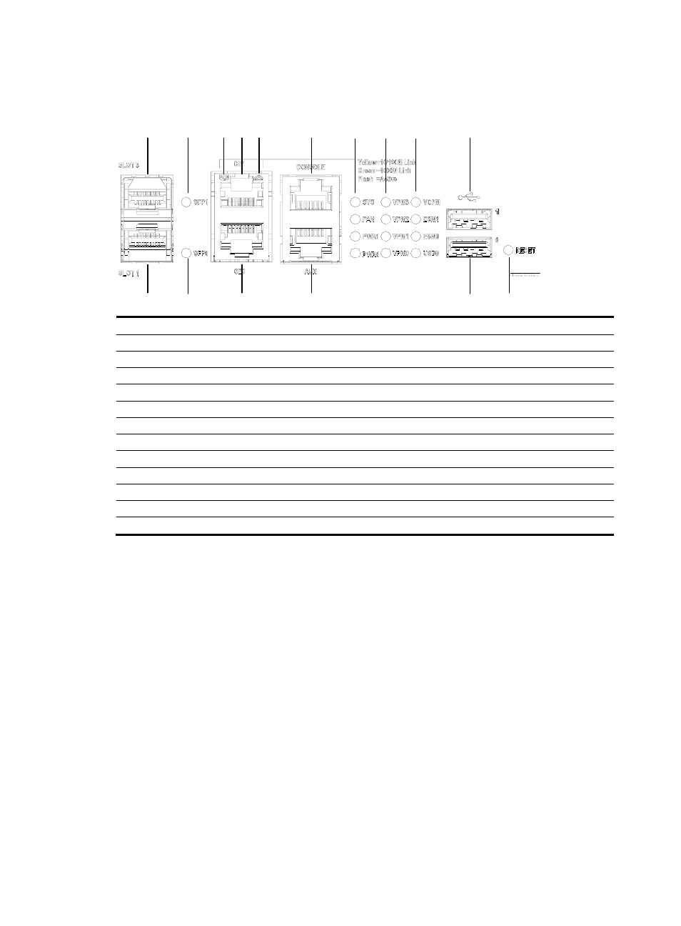
Figure 9 Big view of the LEDs and interfaces on an MPUF
(1)
(2)
(3)
(4)
(5)
(6)
(7)
(8)
( 9 )
(10)
(11)
(12)
(13)
(15)
(16)
(17)
(18)
(14)
(19)
(20)
(22)
(21)
(23)
(24)
(25)
(1) System LED (SYS)
(2) Fan LED (FAN)
(3) Power LED 1 (PWR1)
(4) Power LED 0 (PWR0)
(5) VPM LED 3 (VPM3)
(6) VPM LED 2 (VPM2)
(7) VPM LED 1 (VPM1)
(8) VPM LED 0 (VPM0)
(9) VCPM LED (VCPM)
(10) ESM LED 1 (ESM1)
(11) ESM LED 0 (ESM0)
(12) USB Slave LED (USB0)
(13) Fixed gigabit electrical interface 0 LED
(14) Fixed gigabit electrical interface 1 LED
(15) Fixed gigabit optical interface 0 LED
(16) Fixed gigabit optical interface 1 LED
(17) USB interface 0
(18) USB interface 1
(19) Console port (CONSOLE)
(20) Auxiliary port (AUX)
(21) Fixed gigabit electrical interface 0
(22) Fixed gigabit electrical interface 1
(23) Fixed gigabit optical interface 0
(24) Fixed gigabit optical interface 1
(25) RESET LED