Installing generic modules, Connecting the pgnd – H3C Technologies H3C MSR 50 User Manual
Page 30
22
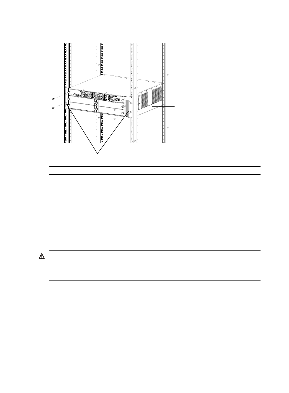
Figure 17 Installing MSR 50 Router in a rack
(1)
(2)
(1) Mounting brackets
(2) Guide rail
Installing Generic Modules
Installing generic modules includes installing the main control board, PSUs, the FAN module, and FICs.
For more information about the main control board, PSUs, FAN module and their installation, refer to
Chapter 6 “Hardware Maintenance” in this manual. For more information about FICs and their
installation, refer to MSR Series Routers Interface Module Manual.
Connecting the PGND
WARNING!
The correct connection of the protection ground (PGND) cable on the router chassis is an essential
safeguard against lightning strokes and EMI. You need to correctly connect the PGND cable when
installing or using the router.
As shown in the following figure, the router provides a protection ground (PGND) screw at the top
right-rear of the chassis. You must securely connect it to the earth ground to safely channel faradic current
and leakage electricity to the ground and have the device less susceptible to electromagnetic
interference (EMI).This PGND wire can also protect the router against the lightning caused by the
connection with the external network lines, such as E1/T1 line, ISDN/PSTN line.
The grounding screw of MSR 50 Router, which is marked with grounding label, is located near the AC
power socket and its switch on the rear panel of the chassis, as shown in the following figure: