Msr 30-10 router, Appearance – H3C Technologies H3C MSR 30 User Manual
Page 11
3
Item
MSR
30-10
MSR
30-11
MSR
30-11E
MSR
30-11F
MSR
30-16
MSR
30-20
MSR
30-40
MSR
30-60
DC input
Rated
voltage
range:
–48
VDC to
–60
VDC
Not
support
ed
Not
support
ed
Not
supporte
d
Not
support
ed
Rated
voltage
range:
–48
VDC to
–60
VDC
Rated
voltage
range:
–48
VDC to
–60
VDC
Rated
voltage
range:
–48
VDC to
–60
VDC
PoE input
Not supported
Rated voltage range: 100 VAC to 240
VAC, 50 Hz or 60 Hz
Maximum power
54 W
54 W
54 W
54 W
100 W
125 W 210 W 210 W
Operating temperature 0°C to 40°C (32°F to 104°F)
Relative humidity
(non-condensing)
5% to 90%
NOTE:
•
The console port and AUX port of the MSR 30-10/30-11/30-11E/30-11F share the same physical port.
•
Boot ROM stores the Bootstrap for booting the router.
•
The memory is used to store the communication data between the system and the CPU when the system
is running.
•
The CF card is used to store the software system and configuration file. The CF card LED blinks when the
system is reading/writing data from/to the CF card. In this case, do not remove the CF card, otherwise
hardware and software damage may occur.
•
Do not unplug the USB device during USB data transmission; otherwise, data loss or even hardware
failures may occur.
•
The USB interface does not support hot-swapping of USB modems from Sierra Wireless.
MSR 30-10 Router
Appearance
1.
Front view
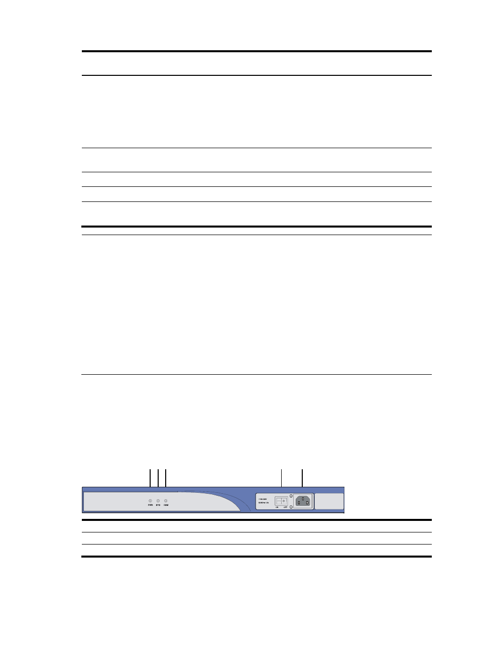
Figure 1 Front panel of an MSR 30-10
(1)
(5)
(4)
(3)
(2)
(1) Power LED (PWR)
(2) System LED (SYS)
(3) ESM LED
(4) Power switch
(5) Power receptacle