Msr 30-20 router, Appearance – H3C Technologies H3C MSR 30 User Manual
Page 18
10
LED Description
ESM0 to 1
•
OFF means no ESM is in the ESM slot.
•
Solid green means an ESM is in the ESM slot and operates normally.
•
Blinking green means the ESM is processing data.
•
Solid yellow means an ESM is in the ESM slot but does not operate normally.
VCPM
•
OFF means VCPM is not in the slot.
•
Steady green means a VCPM is in the slot and operates normally.
•
Steady yellow means a VCPM is in the slot but does not operate normally.
VPM0 to 1
•
OFF means no VPM is in the VPMx slot.
•
Steady green means a VPM is in the VPMx slot and operates normally.
•
Steady yellow means a VPM is in the VPMx slot but does not operate normally.
MSR 30-20 Router
Appearance
1.
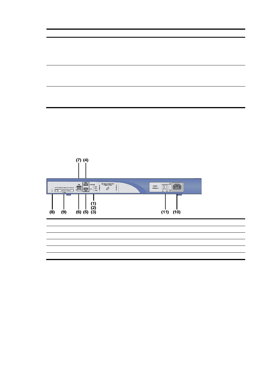
Front view
Figure 11 Front view of an MSR 30-20
(1) Power LED (PWR)
(2) System LED (SYS)
(3) USB LED
(4) Console port (CONSOLE)
(5) Auxiliary port (AUX)
(6) USB interface 0
(7) USB interface 1
(8) CF card LED
(9) CF card
(10) Power socket
(11) Power switch