Msr 30-11 router, Appearance, Panel leds – H3C Technologies H3C MSR 30 User Manual
Page 13
5
MSR 30-11 Router
Appearance
1.
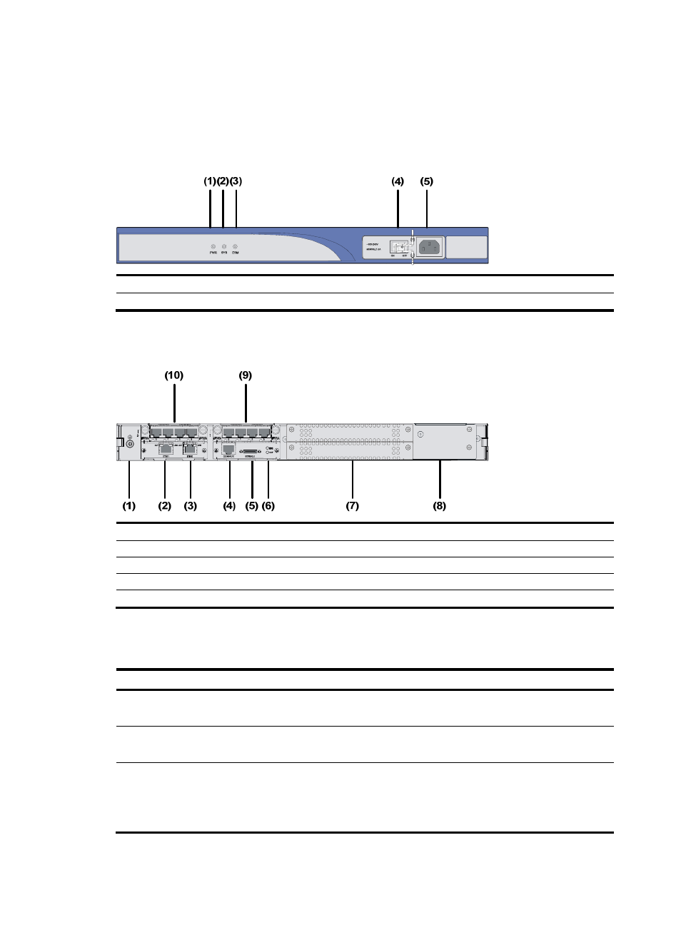
Front view
Figure 3 Front panel of an MSR 30-11
(1) Power LED (PWR)
(2) System LED (SYS)
(3) ESM LED
(4) Power switch
(5) Power receptacle
2.
Rear view
Figure 4 Rear panel of an MSR 30-11
(1) Grounding terminal
(2) FE interface 1
(3) FE interface 0
(4) Console/AUX interface
(5) Serial interface
(6) Serial interface status LEDs
(7) MIM/XMIM slot
(8) Removable slide rails
(9) SIC slot 1
(10) SIC slot 2
Panel LEDs
Table 4 LEDs on the front panel of an MSR 30-11
LED Description
PWR
•
ON: The power supply of the system works normally.
•
OFF: The power supply of the system is disconnected.
SYS
•
Blinking: The system runs normally.
•
ON or OFF: The system runs abnormally.
ESM
•
OFF: No ESM is in position.
•
Solid green: An ESM is in position and works normally.
•
Blinking green: The ESM is processing data.
•
Solid yellow: An ESM is in position but is faulty.