Panel leds – H3C Technologies H3C MSR 30 User Manual
Page 17
9
2.
Rear view
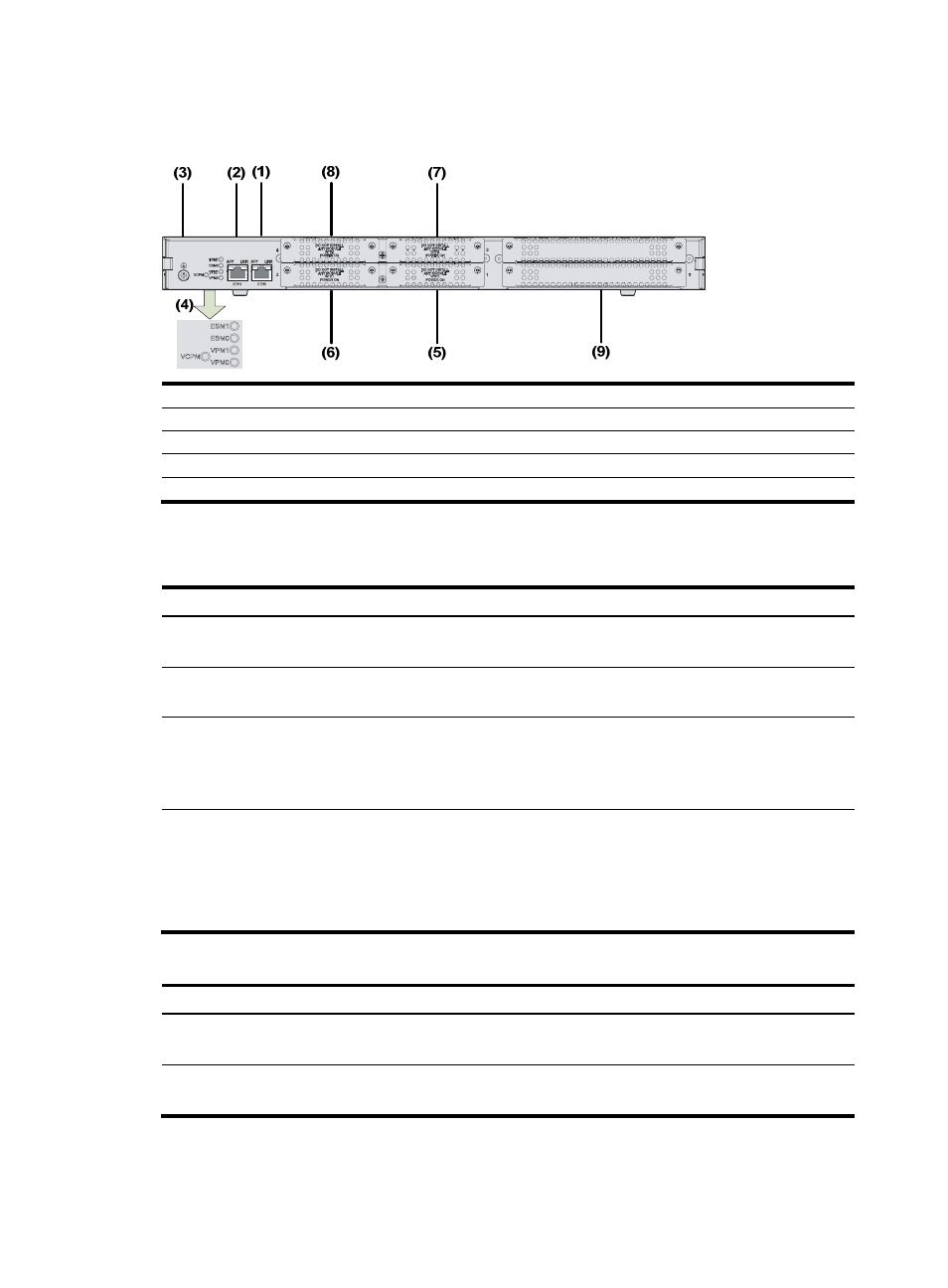
Figure 10 Rear view of an MSR 30-16
(1) FE interface 0
(2) FE interface 1
(3) Grounding terminal
(4) LEDs
(5) SIC slot 1
(6) SIC slot 2
(7) SIC slot 3
(8) SIC slot 4
(9) MIM slot 5
Panel LEDs
Table 8 Front panel LEDs of an MSR 30-16 router
LED Description
PWR
•
ON means: the system provides power for cards normally.
•
OFF means the system does not supply power for cards.
SYS
•
Blinking means the system is operating normally.
•
Steady ON or steady OFF means the system does not operate normally.
USB0
•
OFF means the USB interface has not been connected to a host.
•
Steady green means the USB interface is connected to a host and the host can be removed.
•
Blinking green means data is being transferred to/from the host and the host cannot be
removed now.
CF
CF card LED:
•
Steady green means the CF card is in place and can be identified by the router.
•
Blinking green means the CF card is being accessed and must not be removed.
•
Steady yellow means the CF card is in place but cannot be identified by the router.
•
OFF means no CF card is inserted or the CF card cannot be identified.
Table 9 Rear panel LEDs of an MSR 30-16 router
LED Description
LINK
•
OFF means no link is present.
•
ON means a link connection is established.
ACT
•
OFF means no data is being received or sent.
•
ON means data is being received or sent.