Msr 30-11e router, Appearance, Panel leds – H3C Technologies H3C MSR 30 User Manual
Page 14
6
Table 5 LEDs on the rear panel of an MSR 30-11
LED Description
LINK
•
OFF: No link is present.
•
ON: A link is present.
ACT
•
OFF: No data is being received or sent.
•
Blinking: Data is being received or sent.
MSR 30-11E Router
Appearance
1.
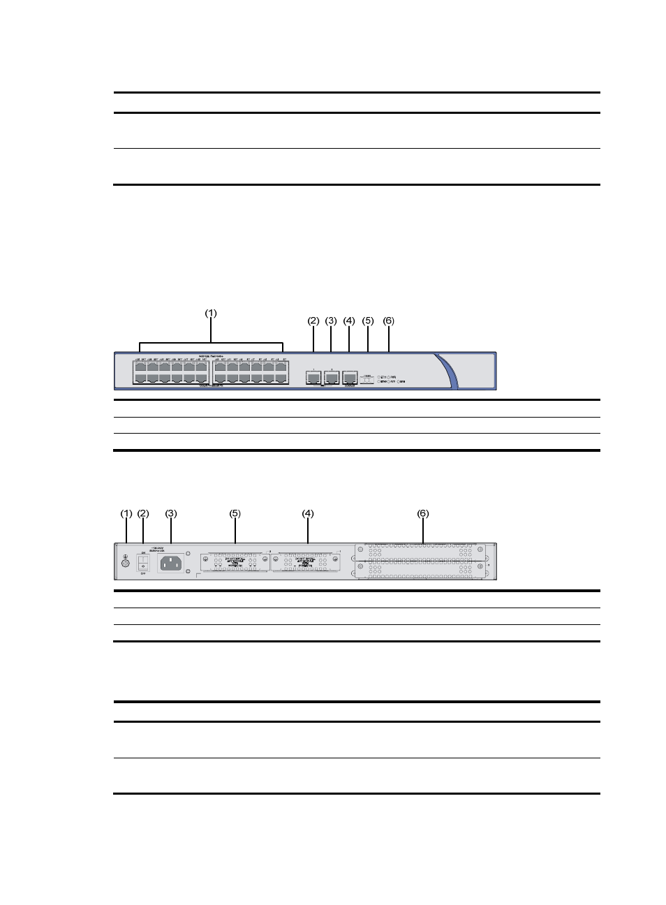
Front view
Figure 5 Front view of an MSR 30-11E
(1) 24 FE switching interfaces
(2) ETH interface 1
(3) ETH interface 0
(4) Console/AUX interface
(5) USB interface
(6) LEDs
2.
Rear view
Figure 6 Rear view of an MSR 30-11E
(1) Grounding terminal
(2) Power switch
(3) Power receptacle
(4) SIC slot 1
(5) SIC slot 2
(6) MIM/XMIM slot
Panel LEDs
Table 6 Front panel LEDs of an MSR 30-11E router
LED Description
PWR
•
ON means: the system provides power for cards normally.
•
OFF means the system does not supply power for cards.
SYS
•
Blinking means the system is operating normally.
•
Steady ON or steady OFF means the system does not operate normally.