Slot arrangement, Panel leds – H3C Technologies H3C MSR 30 User Manual
Page 21
13
2.
Rear view
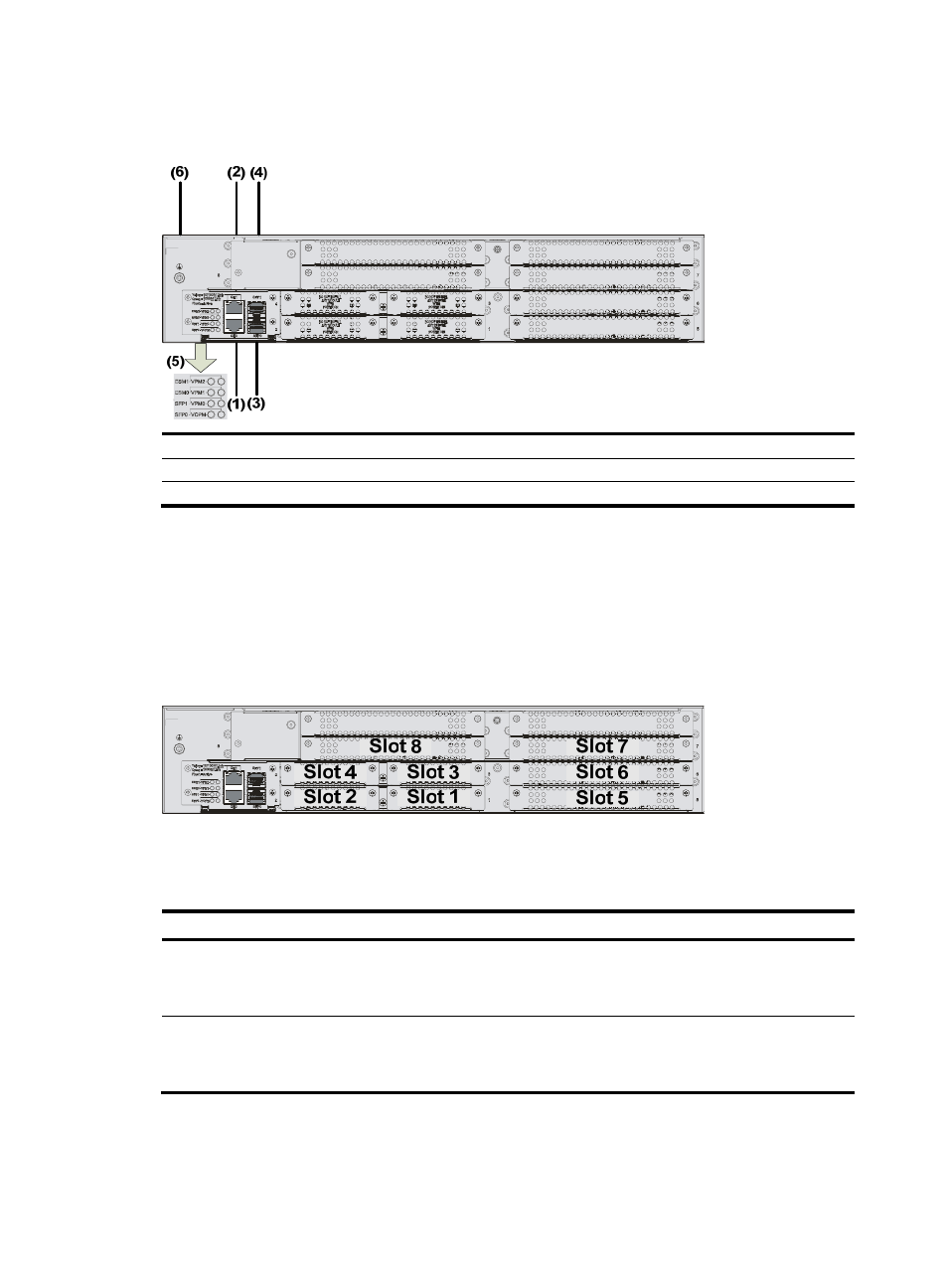
Figure 14 Rear view of an MSR 30-40
(1) GE interface 0
(2) GE interface 1
(3) SFP0 port
(4) SFP1 port
(5) LEDs
(6) Grounding terminal
Slot arrangement
As a self-developed 2U device, each MSR 30-40 router provides four SIC slots and four MIM slots
respectively, delivering expansion of access and service capabilities. In addition, the SIC slide rail
between Slot 1 and Slot 2 can be removed so that two SIC slots can be extended to form a DSIC slot.
Similarly, Slot 3 and Slot 4 can be arranged to form another DSIC slot, and Slot 7 and Slot 8 can be
arranged to serve as a DMIM slot.
Figure 15 Slots on an MSR 30-40 router
Panel LEDs
Table 12 Front panel LEDs of an MSR 30-40 router
LED Description
PWR
Power LED:
•
ON means the system provides power for cards normally.
•
OFF means the system does not supply power for cards.
SYS
Hardware system operation LED
•
Blinking means the system is operating normally.
•
Steady ON or steady OFF means the system does not operate normally.