SMA TCS 500SC-JP User Manual
Page 11
SMA Solar Technology AG
4 Product Description
Installation Manual
TCS-JP-IA-en-10
11
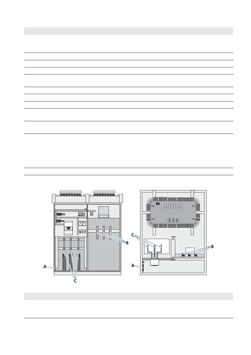
Connection Areas of the Transformer Compact Station
Figure 4: Overview of the connection areas in the Transformer Compact Station (front and top view)
Position Designation
Explanation
A
Low-voltage power switch
Connects the Transformer Compact Station to the inverter.
The low-voltage power switch is used to disconnect the
Transformer Compact Station from the inverter.
B
Fan control contactor
50 Hz or 60 Hz
C
Fan control contactor
50 Hz or 60 Hz
D
Thermostat
Settings for the temperature range for the fans
E
Light repeater transformer alarm
This light repeater indicates when the temperature of the transformer
has exceeded 100°C.
F
Low-voltage transformer
Transformer for supplying the station fans
G
Circuit breaker for fan supply
Primary protection of the low-voltage transformer
H
Circuit breaker for fan supply
Secondary protection of the low-voltage transformer
I
Reset push button for transformer
warning
By pushing this button, the transformer alarm is reset and the light
repeater (E) goes out.
K
Transformer alarm push button for
light repeater test
By pushing the button, the functioning of the light repeater (E) can be
tested.
L
Selection switch for fan control
(ON/OFF/AUTO)
This selection switch sets the operating mode of the fans:
ON: fans are activated
OFF: fans are deactivated
AUTO: fans are switched on or off automatically based on
temperature
M
High-voltage transformer
Converts low voltage into high voltage
Position Designation
Explanation
A
Connecting terminal plate for station
supply, inverter supply and
transformer protection unit
The external voltage supply of the station as well as the supply line to
the inverter and the transformer protection signal line are connected
to this connecting terminal plate.