8 inserting the ac cables – SMA TCS 500SC-JP User Manual
Page 32
7 Electrical Connection
SMA Solar Technology AG
32
TCS-JP-IA-en-10
Installation Manual
7.8 Inserting the AC Cables
Requirement for cable routing:
☐ The low-voltage cables are bundled in the three-phase system.
☐ Between the low-voltage power switch and the inverter, there are, depending on the design, three or four separate
cable routes (e.g., cable channels) for the AC cables. Note that after building the foundation and positioning the
Transformer Compact Station, it will be necessary to excavate cavities underneath the foundation for the cables to
be laid to the enclosure openings.
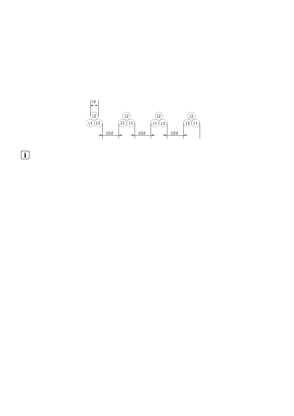
☐ The space between the cable routes must be at least twice the diameter of an AC cable.
Figure 19: Arrangement of AC cables with four cables per line conductor (example).
Procedure:
1. Clean the contact surfaces (see Section 7.5, page 25).
2. Insert the cables in the Transformer Compact Station:
– Cables connecting the high-voltage switchgear to the grid-connection point
– Cables connecting the low-voltage power switch to the inverter
– Cables for the internal power supply of the inverter
– Cables of the transformer protection unit
– Cable for the external supply voltage of the Transformer Compact Station
Observe cable clearances
Lay one line conductor L1, L2 and L3 in each low-voltage cable route. Ensure that the space between the cable
bundles is at least double that of the diameter of a cable. This will prevent the cables from overheating.
Alternate swapping of the line conductors L1 and L3 prevents current imbalances.