SMA POWER REDUCER BOX User Manual
Page 29
Advertising
SMA Solar Technology AG
7 Connection
User Manual
REDUCERBOX-BA-en-16
29
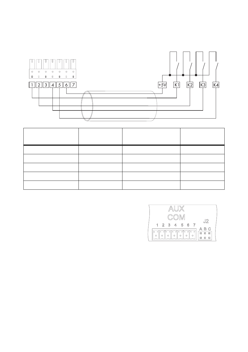
1. Connect the prefabricated cable to the ripple control receiver. The wiring is shown in the
following circuit diagram.
2. Plug the 7-pole plug into the AUXCOM terminal on
the Power Reducer Box.
☑ The Power Reducer Box is connected to the ripple control receiver.
Insulated wire colour*
* DIN 47100 without colour repetition
Signal
Power Reducer Box
AUXCOM terminal
Description
grey
+5 V
6
Voltage Supply
white
K1
1
Relay contact 1
brown
K2
2
Relay contact 2
green
K3
4
Relay contact 3
yellow
K4
5
Relay contact 4
Advertising
See also other documents in the category SMA Equipment:
- SUNNY PORTAL (75 pages)
- SB 2.5-1VL-40 (60 pages)
- SB 2.5-1VL-40 Service Manual (36 pages)
- SB 240 (78 pages)
- FLX Pro 17 (12 pages)
- FLX Series GSM Option Kit (48 pages)
- FLX Series Sensor Interface Option (51 pages)
- FLX Series PLA Option (62 pages)
- FLX Series (248 pages)
- 25000TL (52 pages)
- 25000TL Installation (40 pages)
- 25000TL Service Manual (46 pages)
- CBL-DC-CMB8-10 (24 pages)
- 25000TL Quick Installation Guide (36 pages)
- STP 60-10 Replacing a Defective Fan (12 pages)
- STP 60-10 Replacing Defective Surge Arresters (12 pages)
- Webconnect Systems in SUNNY PORTAL (69 pages)
- STP 12000TL (68 pages)
- STP 60-US-10 Installation (232 pages)
- 485 Data Module Type B (24 pages)
- STP 12000TL Quick Installation Guide (28 pages)
- 1000-US (52 pages)
- STP 24000TL-US (78 pages)
- STP 17000TL (60 pages)
- STP 20000TL (2 pages)
- SB 6000TL Service Manual (46 pages)
- MULTIFUNCTION RELAY (32 pages)
- SB 5000TL (60 pages)
- SB 5000TL Quick Installation Guide (32 pages)
- FANKIT01-10 (24 pages)
- SB 7700TL-US (28 pages)
- FANKIT02-10 (24 pages)
- SB 7700TL-US Installation (96 pages)
- SUNNY MINI CENTRAL (48 pages)
- DC Disconnect Switch For SB 3800-U (32 pages)
- SB 4000-US (100 pages)
- DB-DC-DISCON (4 pages)
- SB 3800-U (86 pages)
- POWER BALANCER (28 pages)
- SB 8000-US (104 pages)
- SB 11000TL‑US (40 pages)
- SMC 11000TL (24 pages)
- SBCBTL6 (36 pages)
- SB 11000TL‑US Installation (92 pages)
- SMC 11000TL Installation (96 pages)