5 communication, 1 routing cables into the automatic switch box, Communication – SMA AUTOMATIC SWITCH BOX XL User Manual
Page 39: Routing cables into the automatic switch box
SMA Solar Technology AG
Electrical Connection
Installation Guide
AS-BOX-XL-IEN094410
39
5.5 Communication
The Automatic Switch Box transfers voltage measurement and current measurement signals to the
Sunny Backup units. These signals are transferred via the supplied control cables and sensor cables
(red). The Automatic Switch Box is controlled by the Sunny Backup-Master in the Main Cluster via a
CAN bus.
Before you can connect the control, sensor and communication cables in the Automatic Switch Box,
you must route the cables into the interior of the Automatic Switch Box through the two-part cable
openings. To do this, proceed as described in Section 5.5.1 ”Routing cables into the Automatic Switch
Box” (page 39). Then connect the cables as described in Section 5.5.2 ”Connecting the control and
sensor cables” (page 42) and Section 5.5.3 ”Connecting the communication cable” (page 42).
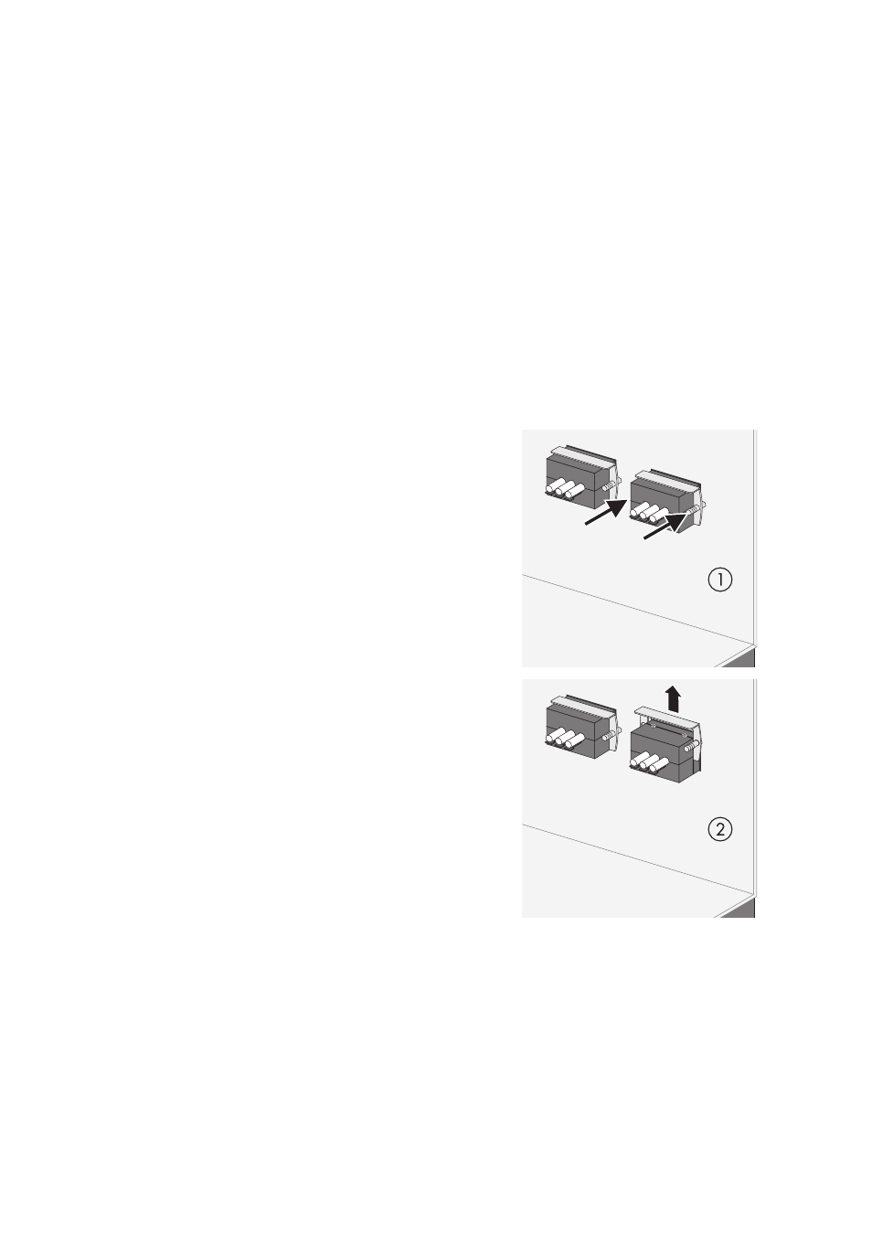
5.5.1 Routing cables into the Automatic Switch Box
1. Loosen the screws on the mounting plate of the two-
part cable opening inside the Automatic Switch
Box.
2. Remove the mounting plate and place it aside.