Modify tag names – Yaskawa Tag Generator User Manual
Page 14
Dialog Field
Description
Node Name (Textbox):
Enter the name of the node in this text box to match the node name in Logix Designer/
RSLogix 5000.
Module Slot # (Textbox):
Specify the slot number of the module that will indirectly reference the DeviceNet tags.
Location (Textbox):
Enter "Local" in this textbox if the DeviceNet scanner is on the same chassis as the CPU.
Otherwise enter the name of the remote scanner/adapter in this textbox.
Input and Output Assembly Offsets
(Textbox, 2 each):
Enter the Input and Output Assembly offsets to match the data mapping location within the
PLC memory.
NOTICE: Abnormal Equipment Operation. Ensure the Input and Output Assembly
offset values match the data mapping location in the PLC memory. Invalid or
mismatched values will report improper data back to the tags and may cause erroneous
operation.
Include COS (Checkbox):
Select this checkbox to include the “Change of State” data if required.
COS Offset (Textbox):
Enter the offset value to match the data mapping location in the PLC memory when the
“Include COS” checkbox is selected.
u
Modify Tag Names
The Tag Generator provides the option to modify tag names and descriptions to for each application. Follow these steps to
modify tag names.
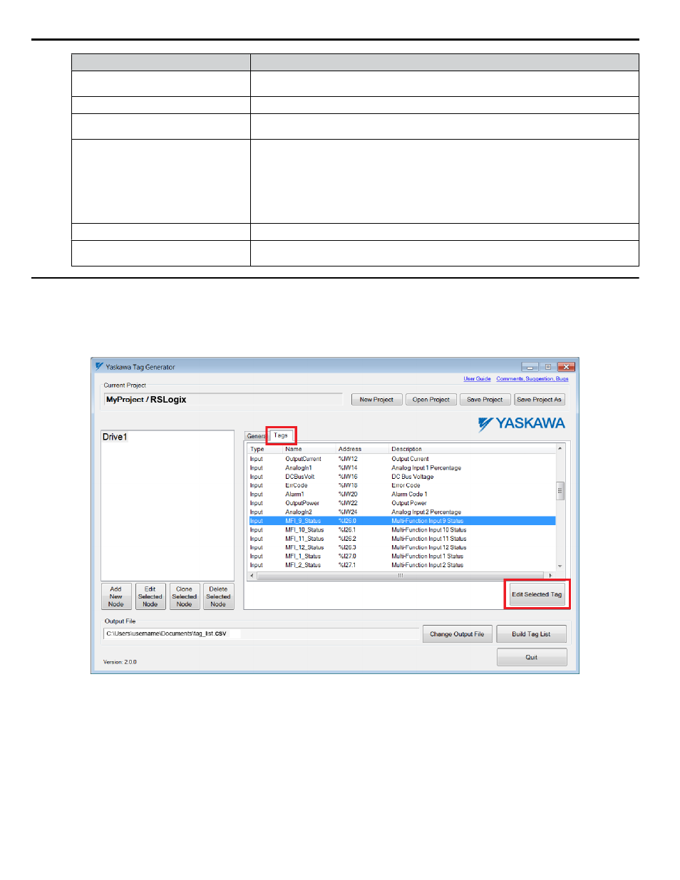
1.
Select the “Tags” tab in the “Yaskawa Tag Generator” dialog, then select a tag to edit and click the “Edit Selected
Tag” button to display the "Edit Tag" dialog.
Figure 7 Yaskawa Tag Generator Dialog
4 EtherNet/IP or DeviceNet Projects
14
YASKAWA TOEP YAICOM 20A Tag Generator User Guide