A1000, Drive – Yaskawa Modbus TCP/IP Installation User Manual
Page 22
5 Installation Procedure
22
YASKAWA ELECTRIC TOBP C730600 57B 1000-Series Option SI-EM3 Installation Manual
6.
Connect the Ethernet communication cable to the option modular connector (CN1).
To connect the option to a network, insert the RJ45 communication connector of the
Cat 5e patch cable into the option modular female connector (CN1). Ensure the
cable end is firmly connected (see
Communication Cable Specifications
Only use cable recommended for Modbus TCP/IP™. Using a cable not specifically
recommended may cause the option or drive to malfunction.
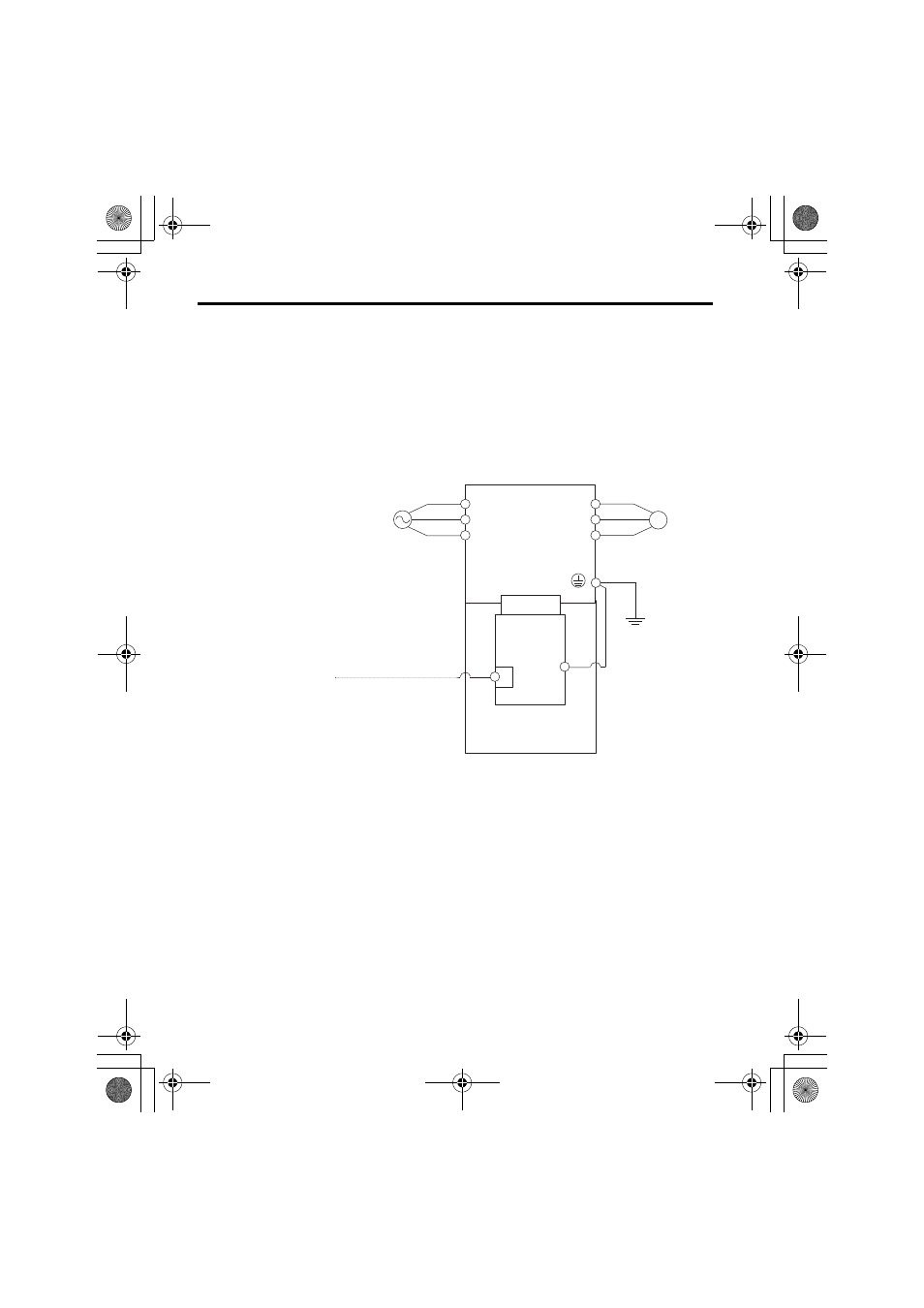
Connection Diagram
Figure 8 Option Connection Diagram
<1> The ground wire provided in the option shipping package must be connected during installation.
Drive
M
U
V
W
R
S
T
CN5-A
FE
<1>
ModbusTCP/IP Master Modbus TCP/IP Cable
Motor
Power
SI-EM3
Modbus
TCP/IP
Option
CN1
A1000
Modbus_IM_E_conditional.fm 22 ページ 2012年10月31日 水曜日 午後1時45分