6 related drive parameters – Yaskawa Modbus TCP/IP Installation User Manual
Page 33
6 Related Drive Parameters
YASKAWA ELECTRIC TOBP C730600 57B 1000-Series Option SI-EM3 Installation Manual
33
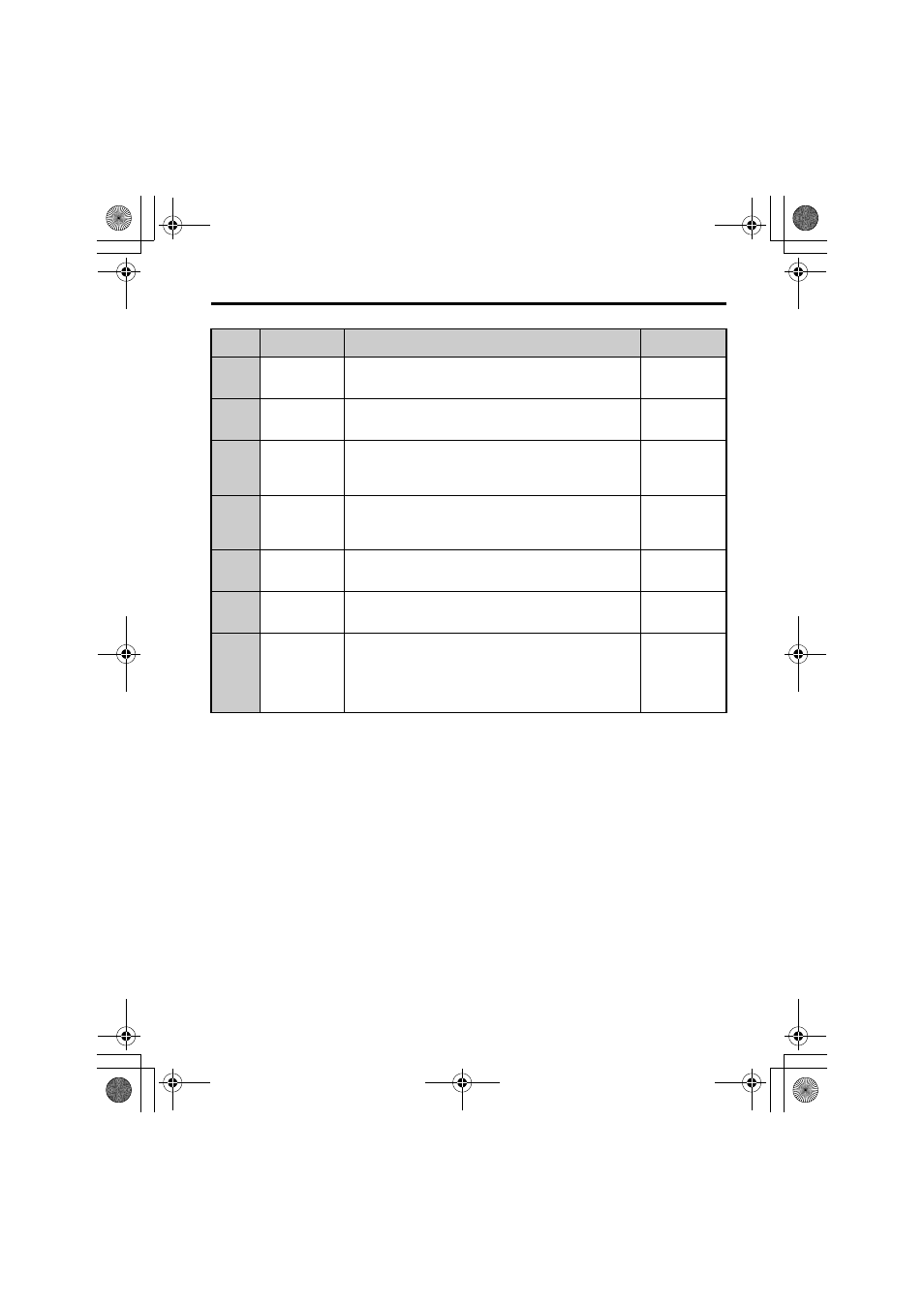
F7-11
(3EF)
Gateway Address
3
Sets the static/fixed Gateway address.
Parameter F7-11 sets the third most significant octet.
Default: 1
Range: 0 to 255
F7-12
(3E0)
Gateway Address
4
Sets the static/fixed Gateway address.
Parameter F7-12 sets the fourth most significant octet.
Default: 1
Range: 0 to 255
F7-13
(3F1)
Address Mode at
Startup
Selects how the option address is set.
0: Static
1: BOOTP
2: DHCP
Default: 2
Range: 0 to 2
F7-14
(3F2)
Duplex Mode
Selection
Selects duplex mode setting.
0: Half duplex forced
1: Auto-negotiate duplex mode and communication speed
2: Full duplex forced
Default: 1
Range: 0 to 2
F7-15
(3F3)
Communication
Speed Selection
Sets the communication speed.
10: 10 Mbps
100: 100 Mbps
Default: 10
Range: 10, 100
F7-16
(3F4)
Communication
Loss Time-out
Sets the time-out value for communication loss detection in tenths
of a second. A value of 0 disables the connection time-out.
Example: An entered value of 100 represents 10.0 seconds.
Default: 0
Min.: 0
Max.: 300
H5-11
(43C)
Communications
ENTER Function
Selection
Select the function for the ENTER command that saves parameter
data to the drive.
0: Parameter changes are activated when ENTER command is
written
1: Parameter changes are activated immediately without use of
ENTER command
Default: 1
Range: 0, 1
<1> To start and stop the drive with the option master device using serial communications, set b1-02 to 3. To control
the drive frequency reference via the master device, set b1-01 to 3.
<2> If F6-01 is set to 3, the drive will continue to operate when a fault is detected. Take safety measures, such as
installing an emergency stop switch.
<3> A1000: Enabled in CLV, AOLV/PM, and CLV/PM control modes (A1-02 = 3, 6, or 7). When enabled, d5-01
determines whether the value is read as the Torque Limit value (d5-01 = 0) or read as the Torque Reference value
(d5-01 = 1). In CLV/PM, this value is read as the Torque Limit.
Z1000: Enabled in OLV/PM control modes (A1-02 = 5). When enabled, d5-01 determines whether the value is
read as the Torque Limit value (d5-01 = 0) or read as the Torque Reference value (d5-01 = 1). In V/f, this value
is read as the Torque Limit.
<4> The setting specifies that the Torque Reference or Torque Limit is to be provided via network communications
(F6-06 = 1). The motor may rotate if no torque reference or Torque Limit is supplied from the PLC.
<5> Cycle power for setting changes to take effect.
<6> If F7-13 is set to 0, then all IP Addresses (F7-01 to F7-04) must be unique.
<7> Set F7-01 to F7-12 when F7-13 is set to 0.
<8> Set F7-15 when F7-14 is set to 0 or 2.
No.
(Addr. H)
Name
Description
Values
Modbus_IM_E_conditional.fm 33 ページ 2012年11月5日 月曜日 午後4時32分