Example machine configurations – Yaskawa F7 Drive Technical Manual Orientation User Manual
Page 2
Date: 03/03/06, Rev: 06-03
Page 2 of 16
TM.F7SW.063
This document is intended to provide proper installation and use of the Yaskawa drive with custom software. This
document is a supplement to the standard drive technical manual. It describes the effects on the drive parameters
and functions with the software installed. Read and understand this document and the standard drive technical
manuals before attempting to install, adjust, operate, inspect or maintain the drive. Observe all cautions and
warnings in this document and the standard drive technical manuals. Custom software is written to add
functionality to a standard AC drive to enhance or enable use in a specific application. The software is loaded to
the flash ROM area of the control board, and replaces the standard drive software. Custom software can add new
functions, modify standard functions, or even inhibit standard functions. It can be used to modify display text or
parameter names. Custom software is usually loaded to the drive before delivery. The control board and drive
nameplate are assigned unique part numbers and the software is registered, archived, and retrievable.
When seeking support for a drive with custom software, it is imperative to provide the unique part number shown
on the drive nameplate. The software has been flashed to the control board memory and the operation of
parameters, functions, and monitors are different than the standard drive software, as described herein.
1.0 Overview
This orientation software allows an F7 drive to repeatedly stop a machine at a certain point in its rotational cycle.
This is accomplished by means of an orientation (positioning) encoder directly coupled to the machine part to
be positioned. A simple example is to think of the hands on a clock. If the orientation encoder is mounted to the
motor shaft, this software can stop the motor so that the keyway in the motor shaft stops, at say 3 o’clock, every
time. The target applications are equipment that must stop in specific positions including tool changing for
machine tool spindles and die changing for punch/stamping presses. This F7 software is meant to replace the
G5 custom software and MC5 option board versions of the orientation function. Example configurations include:
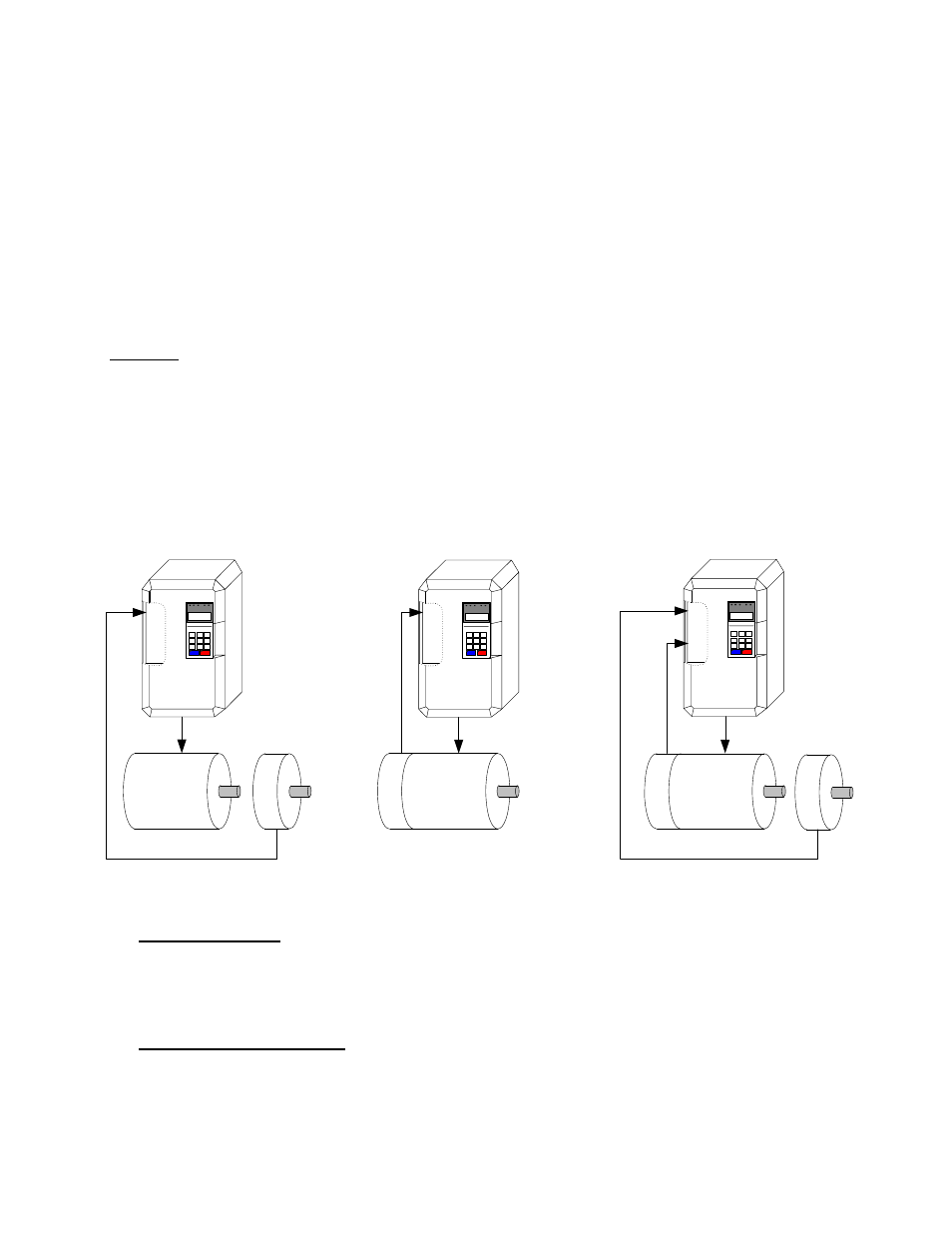
Example Machine Configurations
1.1 Open Loop Control
The open loop V/Hz or open loop vector control method (A1-02 = 0 or 2) may be used when the motor and
the machine part to be oriented (positioned) are connected through a drive train with a constant ratio. A
PG-X2 encoder feedback option card is required to interface with the orientation encoder attached to the
machine part that is being orientated.
1.2 Closed Loop Vector Control
The closed vector loop control method (A1-02 = 3) should be used for the best speed and orientation
characteristics when the drive motor directly drives the machine part being oriented (positioned). When
using this method, the motor encoder is used for both flux vector control and for orientation. A PG-X2
encoder feedback option card is required. This method will provide superior performance than the open
loop method.
PG
-X
2
M
oto
r /
P
os
iti
on
Enc
od
er
Machine
Motor
PG
-W
2
Mot
or
E
nc
oder
Machine
Motor
PG
-X
2
Po
si
tio
n
Enc
oder
3. Closed Loop Control
With Orientation Encoder
2. Closed Loop Control
1. Open Loop Control
Machine
Motor
Pos
iti
on
E
ncoder