Yaskawa G5 Eliminator User Manual
Page 7
Date: 07/01/04, Rev: 04-07
Page 7 of 27
TM.G5SW.015
1.4 Configuring
Examples
This software may be configured just using the quick references. The following examples will
demonstrate that it is just a matter of selecting the needed functions and connecting them
together. Once the configuration is finished just record the connector numbers in the sequence
that starts at the source information and follows it through the operations in the manner that it
must be converted util it is sent to the drive. Then input the connector numbers into the drive.
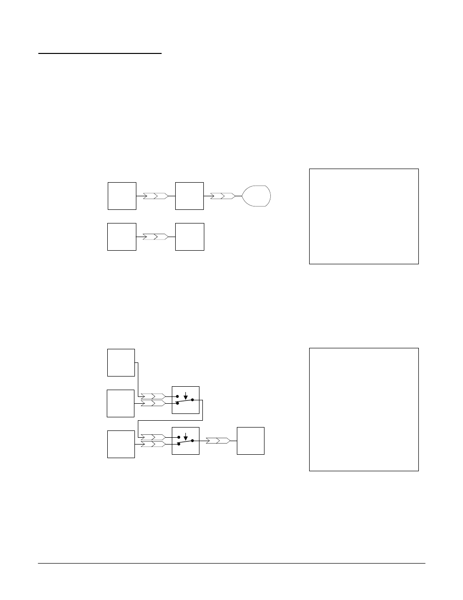
Example 1.4.1:
This configuration will provide a speed reference to the drive and a scaled display
monitor for the machine operator.
Terminal 13
Analog
Input
13
Scale
61
60
U1-54
Monitor
94
Drive
Speed
Control
ff
Terminal 13
Analog
Input
13
Figure 1.4.1
The scaling parameters must be set to control the value displayed by the monitor.
Example 1.4.2:
This configuration uses 2 multi-function inputs to select between the 3 analog inputs to be
used as the speed reference.
Terminal 16
Analog
Input
16
Terminal 14
Analog
Input
14
Terminal 13
Analog
Input
06
04
05
H1- 0x : 81
Switch 2 DI
03
01
02
H1- 0x : 80
Switch 1 DI
13
Drive
Speed
Control
ff
Figure 1.4.2
The multi-function and analog inputs must be setup. The drive will use terminal 13 as a
reference with both switches off. When switch 1 is on via the multi-function input, terminal
14 becomes the reference. When both switches are on via the multi-function inputs, terminal
16 becomes the reference.
Configuration List
13,60,61,94,13,ff, 00
Configure the Drive
A2-11 = 1360
A2-12 = 6194
A2-13 = 13ff
A2-14 = 00XX
XX = Don’t Care
Configuration List
16,04,14,05,06,01,13,02,03,
ff, 00
Configure the Drive
A2-11 = 1604
A2-12 = 1405
A2-13 = 0601
A2-14 = 1302
A2-15 = 03ff
A2-16 = 00XX
XX = Don’t Care