Product transition guide terminal comparison – Yaskawa GPD 515/G5 to F7 User Manual
Page 14
Product Transition Guide
Terminal Comparison
__________________________
PL.F7.02.TransitionGuide 6/5/06
Page 14 of 40
Yaskawa Electric America, Inc
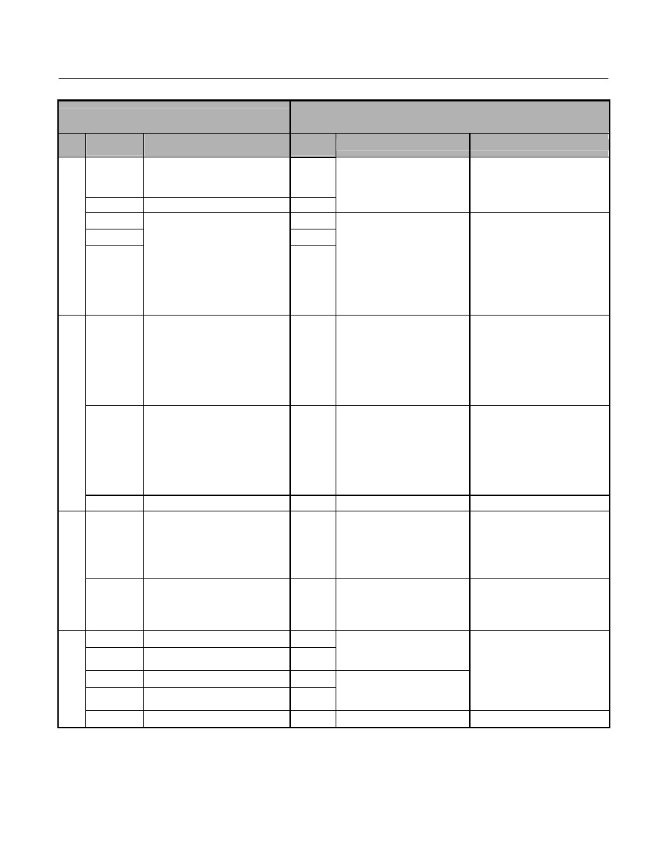
GPD515/G5 Terminal
F7 Terminal
(Designations similar to GPD506/P5)
Type
GPD515/G5
Terminal
Default Function
F7
Terminal
Default Function
F7 Description
26
Speed agree detection
Open collector output
48V, 50mA or less
M5
27
Open collector output common
M6
Frequency agree
(N.O. contact)
Multi-function digital output.
Function set by H2-03.
18
MA
19
MB
20
Fault contact output
(NO/NC contact)
When faulted : Closed between
terminals 18 and 20
Open between terminals
19 and 20
Dry contact capacity: 250VAC
1A or less, 30VDC 1A or less
MC
Fault output signal
(SPDT)
Form C Dry contacts
capacity:
1 A max. at 250Vac
1 A max. at 30Vdc
21
Frequency meter output
0 to ±10V/100% frequency
0 to ±11V Max. ±5%
2mA or less
FM
Output frequency
0 to +10Vdc or
+/-10Vdc 500 ohm input
10V=100%Output frequency
(Max current 2 mA).
4 to 20mA
20mA=100% Output frequency
Function set by H4-01.
23
Current monitor
5V/inverter rated current
AM
Output current
0 to +10Vdc or
-10 to +10Vdc 500 ohm input
10V=100% Drive output
current (Max current 2 mA)
4 to 20mA / 100%
Drive's rated output current /
Function set by H4-04.
Anal
og
O
u
tp
ut
Si
g
n
al
s
22
Common (Current Monitor)
AC
Analog common
–
–
RP
Pulse input
0 to 32kHz (3k ohms) ±5%
High level voltages 3.5 to 13.2
Low level voltages 0.0 to 0.8
Duty Cycle (on/off) 30% to
70% Function set by H6-01.
Pulse I/O
–
MP
Pulse monitor
0 to 32kHz
+5V output
(Load: 1.5k ohms)
Function set by H6-06.
–
R+
–
R-
Modbus communication
Differential input,
PHC isolation
–
S+
–
S-
Modbus communication
Differential output,
PHC isolation
–
RS-
485
/42
2
–
IG
Signal common
–
Digital Output
Signals (continued)