I/o terminal cross reference g5 to g7 – Yaskawa GPD 515/G5 to G7 User Manual
Page 12
Product Transition Guide
GPD515/G5 to G7
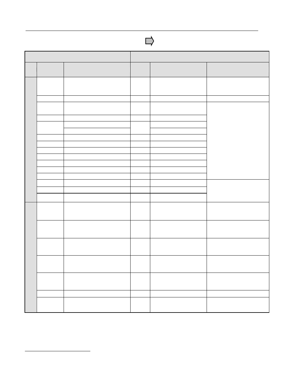
I/O Terminal Cross Reference G5 to G7
GPD515/G5 Terminal
G7 Terminal
Type
GPD515/G5
Terminal
Default Function
G7
Terminal
Default Function
G7 Description
1
Forward run/stop
Signal level: (Photo-coupler
insulated input: +24VDC, 8mA)
S1
Forward run/stop command
–
2
Reverse run/stop
S2
Reverse run/stop command
–
3
External fault input
S3
External fault input
4
Fault reset input
S4
Fault reset
Master/Aux. change
Multi-step speed reference 1
5
Multi-step speed ref.1
S5
(Master/auxiliary switch)
6
Multi-step speed ref.2
S6
Multi-step speed reference 2
7
Jog reference
S7
Jog frequency reference
8
External baseblock
S8
External baseblock N.O.
–
S9
Multi-step speed reference 3
–
S10
Multi-step speed reference 4
–
S11
Accel/Decel time select
–
S12
Emergency Stop N.O.
Multi-function digital inputs
Functions set by:
H1-01 to H1-10.
+24VDC, 8mA
Photo coupler isolation
11
Sequence control input common
SN
Digital input common
–
SC
Factory connected to SP
Digital Input Signals
–
SP
Factory connected to SC
Factory connected for internal
supply, sinking mode.
Refer to G7 User Manual for
other methods.
15
+15VDC Power supply
(20mA maximum)
+V
+15VDC power supply
+15VDC
(20mA maximum)
33
-15VDC Power supply
(20mA maximum)
-V
-15VDC power supply
-15VDC
(20mA maximum)
13
Master frequency ref. (voltage)
-10 to +10VDC (20kohm)
0 to +10VDC (20kohm)
A1
Master frequency reference
0 to +10VDC=100%
0 to +/-10VDC=100% (H3-01)
(20kohm)
14
Master frequency ref. (current)
4 to 20mA (250ohm)
A2
Add to terminal A1
4 to 20mA=100% (250ohm)
0 to +10VDC=100% (20kohm)
Function set by H3-09.
16
Multi-function analog input
-10 to +10VDC (20kohm),
0 to +10VDC (20kohm)
A3
Auxiliary frequency
reference 1
0 to +10Vdc=100%/(20kohm)
0 to +/-10Vdc=100%
Function set by H3-05
17
Common for control circuit 0V
AC
Analog common
–
Analog Input Signals
12
Connection to shield sheath of
signal lead
E(G)
Shield wire, optional ground
line connection point
–
PL.G7.02.TransitionGuide 4/21/04
Page 12 of 38
Yaskawa Electric America, Inc