Physical i/o block terminal layout, Main power terminal comparison, I/o terminal cross reference g5 – Yaskawa GPD 515/G5 to G7 User Manual
Page 14
Product Transition Guide
GPD515/G5 to G7
PL.G7.02.TransitionGuide 4/21/04
Page 14 of 38
Yaskawa Electric America, Inc
I/O Terminal Cross Reference G5
to
G7
GPD515/G5 Terminal
G7 Terminal
Type
GPD515/G5
Terminal
Default Function
G7
Terminal
Default Function
G7 Description
–
RP
Pulse input
0-32kHz (3kohm) ±5%
High level: 3.5-13.2VDC
Low level: 0.0-0.8VDC
Duty Cycle: 30%-70%
Function set by H6-01
Pulse I/O
–
MP
Pulse output
0-32kHz
Output: +5VDC
Load: 1.5kohm
Function set by H6-06
–
R+
–
R-
Modbus RTU protocol
Differential input
PHC isolation
–
S+
–
S-
Modbus RTU protocol
Differential output
PHC isolation
–
RS-485/422
–
IG
Signal common
–
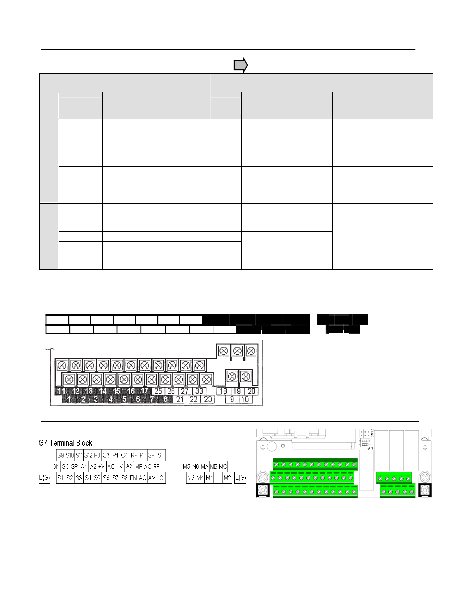
Physical I/O Block Terminal Layout
G5 Terminal Block
1
2
3
4
5
6
7
8
21
22
23
9
10
11
12 (G)
13
14
15
1 6
17
26
2 7
33
25
18
19
20