Input diodes – Yaskawa GPD 506/P5 Section One User Manual
Page 13
Advertising
PP.P5G5.01.Troubleshoot
Page 13
Rev. 06/11/2003
Input Diodes
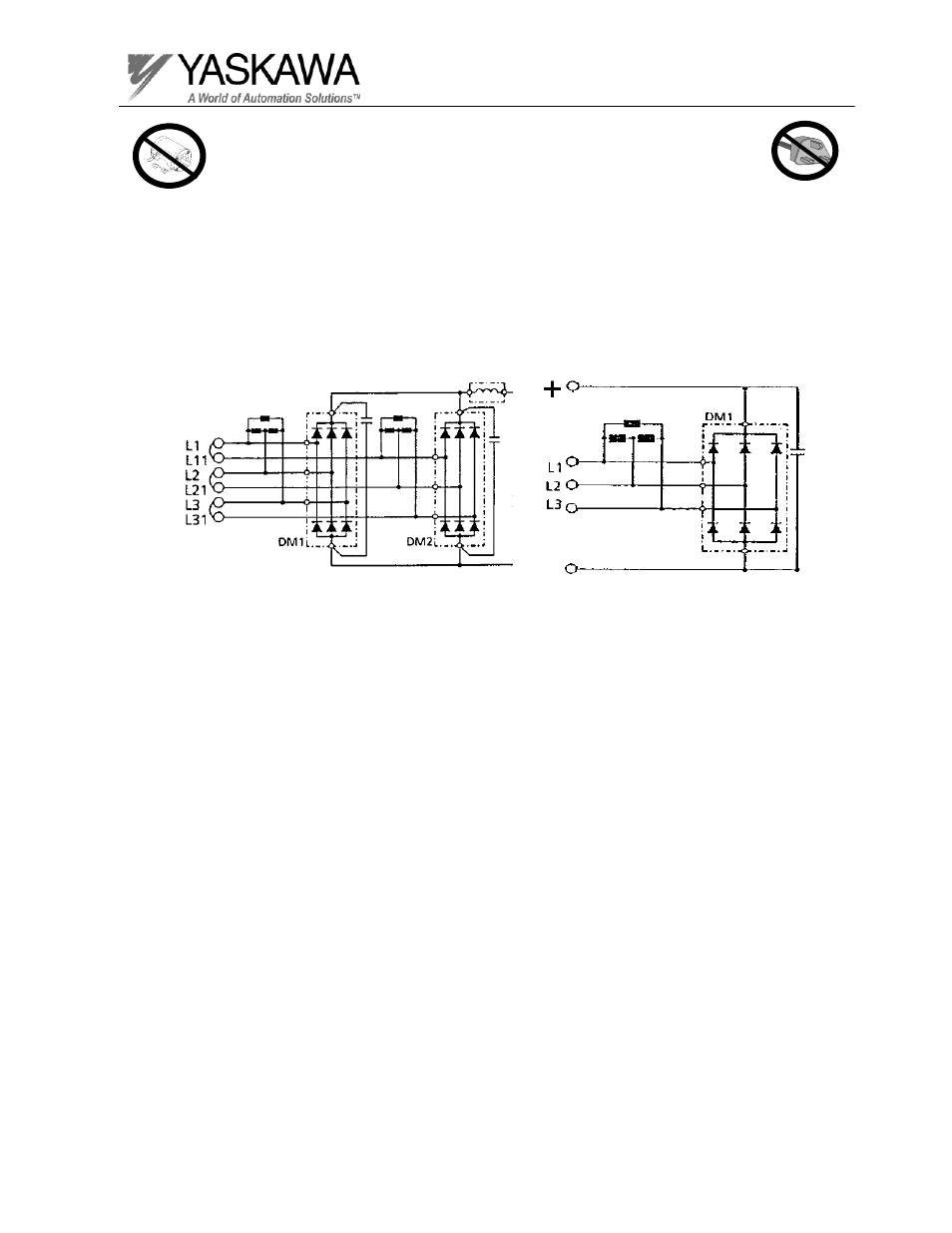
Certain GPD 506/P5 inverters come equipped with a 12 pulse, dual diode input
section. This leads to a reduction of the input current distortion to help meet harmonic
distortion specifications. The schematic diagrams of a dual diode input and a 6 pulse
diode input are shown below.
-
Diode configuration for 6 pulse input
used in GPD 515/G5 inverters.
Diode configuration for 12 pulse input
used in GPD 506/P5 inverters.
Advertising
This manual is related to the following products: