Input diode check – Yaskawa GPD 506/P5 Section One User Manual
Page 16
Advertising
PP.P5G5.01.Troubleshoot
Page 16
Rev. 06/11/2003
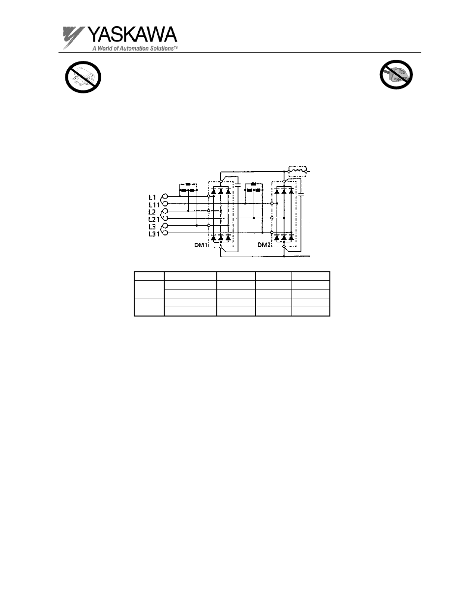
Input Diode Check
Test Equipment - Analog Ohmmeter Set to R X 1 Scale
or Digital Multimeter set to the Diode Check.
Voltage
Model
Connector (-) DC bus (+) DC bus
230V
18kW & 22kW
19CN
Pin 1
Pin 5
30kW ~ 75kW
26CN
Pin 5
Pin 1
460V
18kW ~ 45kW
19CN
Pin 1
Pin 5
55kW ~ 160kW
26CN
Pin 5
Pin 1
For GPD 506/P5 inverters with 12 pulse input, follow the diode check procedure
also checking terminals L11, L21, and L31. Refer to the following list for a test point
for the (-) DC bus and (+) DC bus.
Advertising
This manual is related to the following products: