Braking circuit – Yaskawa GPD 506/P5 Section One User Manual
Page 32
Advertising
PP.P5G5.01.Troubleshoot
Page 32
Rev. 06/11/2003
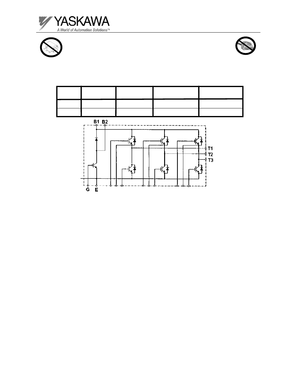
Test Equipment - Analog Ohmmeter Set to R X 1 Scale
or Digital Multimeter set to the Diode Check.
Braking Diode Check
Expected Reading
(Digital Meter)
Step No.
Ohmmeter
Positive Lead
Ohmmeter
Negative Lead
Expected Reading
(Analog Meter)
1
2
Connect to B2
Connect to B2
Connect to B1
Connect to B1
10 Ohms
OL Displayed
0.5-1.5 Volts
Infinite Ohms
* The B1 Terminal is connected to the Positive portion of the DC bus.
Braking Circuit
For 230V 0.4 kW-7.5kW models, 460V 0.4kW-15kW models and 600V 1.5kW-22kW models
Advertising
This manual is related to the following products: