Output transistor check – Yaskawa GPD 506/P5 Section One User Manual
Page 35
PP.P5G5.01.Troubleshoot
Page 35
Rev. 06/11/2003
Output Transistor Check
for models 0.4kw through 15kW
Test Equipment - Analog Ohmmeter Set to R X 1 Scale
or Digital Multimeter set to the Diode Check.
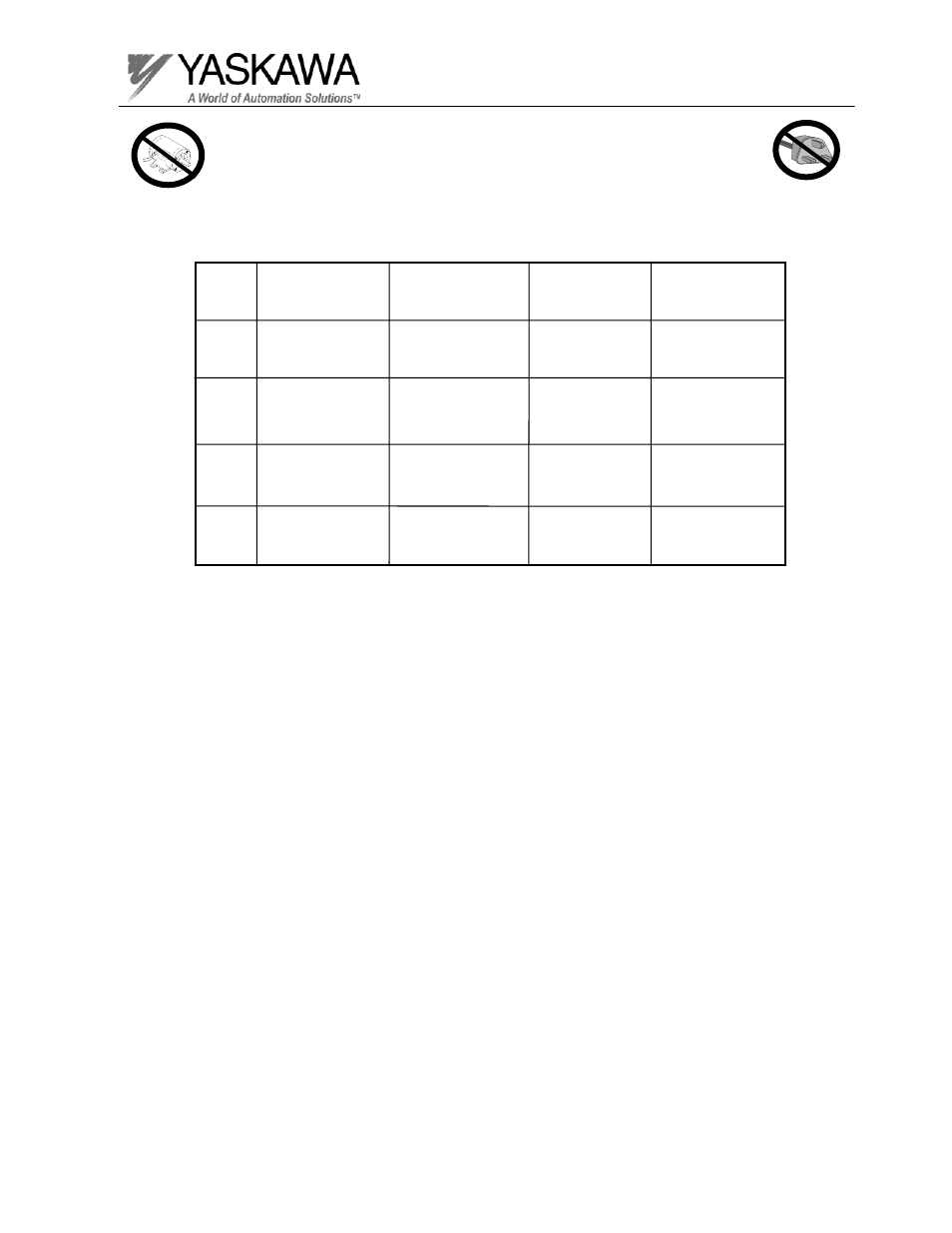
Step No.
Approximately
0.5 Volts
Ohmmeter
Positive Lead
Ohmmeter
Negative Lead
1
2
3
4
T1 Terminal
T2 Terminal
T3 Terminal
Terminal labeled (+)
Approximately
10 Ohms
T1 Terminal
T2 Terminal
T3 Terminal
Terminal labeled (-)
Infinite Ohms
0L displayed
Terminal labeled (-)
T1 Terminal
T2 Terminal
T3 Terminal
Approximately
10 Ohms
Approximately
0.5 Volts
Terminal labeled (+)
T1 Terminal
T2 Terminal
T3 Terminal
Infinite Ohms
0L displayed
Expected
Reading
(Analog Meter)
Expected
Reading
(Digital Meter)
Note: When a transistor fails, all the transistors in the failed phase must be
replaced. They must be replaced with the identical transistor manufacturer and
part number.