Output transistors – Yaskawa GPD 506/P5 Section One User Manual
Page 34
Advertising
PP.P5G5.01.Troubleshoot
Page 34
Rev. 06/11/2003
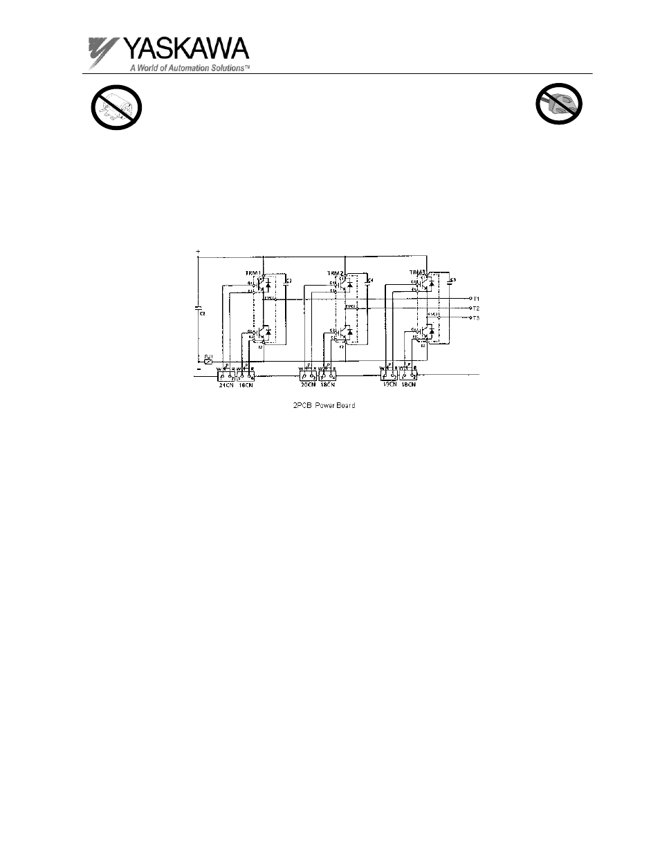
Output Transistors
The transistors can be checked by simply measuring the resistance from the
collector to the emitter. The power transistors used in Yaskawa inverters all have
free-wheeling diodes connected in parallel with the collector-emitter junction.
When measuring the resistance across the output transistors, you should use an
ohmmeter or a digital multimeter and expect to see resistance readings
characteristics of the free-wheeling diode. Resistance should be fairly low in the
forward direction and very high in the reverse direction.
* NOTE: If the DC bus fuse is open, choose a test point for the
negative bus on the output transistor side of the fuse.
Advertising
This manual is related to the following products: