Smartmux board rack address – Yaskawa PLC-5 User Manual
Page 10
HARDWARE
7
SmartMUX Board Rack Address
12/22/94- RD 3196-10
SmartMUX
Board Rack
Address
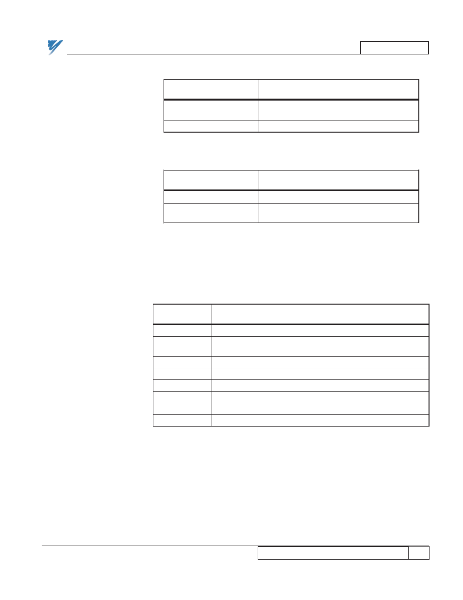
The following DIP switch settings represent the SmartMUX board connected
to the JARC board via the J5 connector.
Table 8. SmartMUX Board Last State Switch
DIP Switch SW1
LAST STATE
Position 4
RESET ALL
X
(DEFAULT)
HOLD ALL
O
X = Closed switch = Switch ON
O = Open switch = Switch OFF
Table 9. SmartMUX Board Watchdog Switch
DIP Switch SW1
WATCHDOG
Position 5
DISABLE WATCHDOG
X
ENABLE WATCHDOG
O
(DEFAULT)
X = Closed switch = Switch ON
O = Open switch = Switch OFF
Table 10. SmartMUX Board Rack Address Selection
DIP Switch / Position
RACK ADDRESS
SW1-6 SW2-1 SW2-2 SW2-3 SW2-4 SW2-5 SW2-6
00
X X X X X X X
01
X X X X O X X
(DEFAULT)
02
X X X O X X X
03
X X X O O X X
04
X X O X X X X
05
X X O X O X X
06
X X O O X X X
07
X X O O O X X
X = Closed switch = Switch ON
O = Open switch = Switch OFF