Yaskawa PLC-5 User Manual
Page 6
HARDWARE
3
JARC Board Setup
12/22/94- RD 3196-10
The JARC board has jumpers and one 12-position DIP switch that are user
configurable.
NOTE: The JARC board only reads the DIP switch settings on
power-up.
The proper version of EPROM must be placed in the EPROM socket.
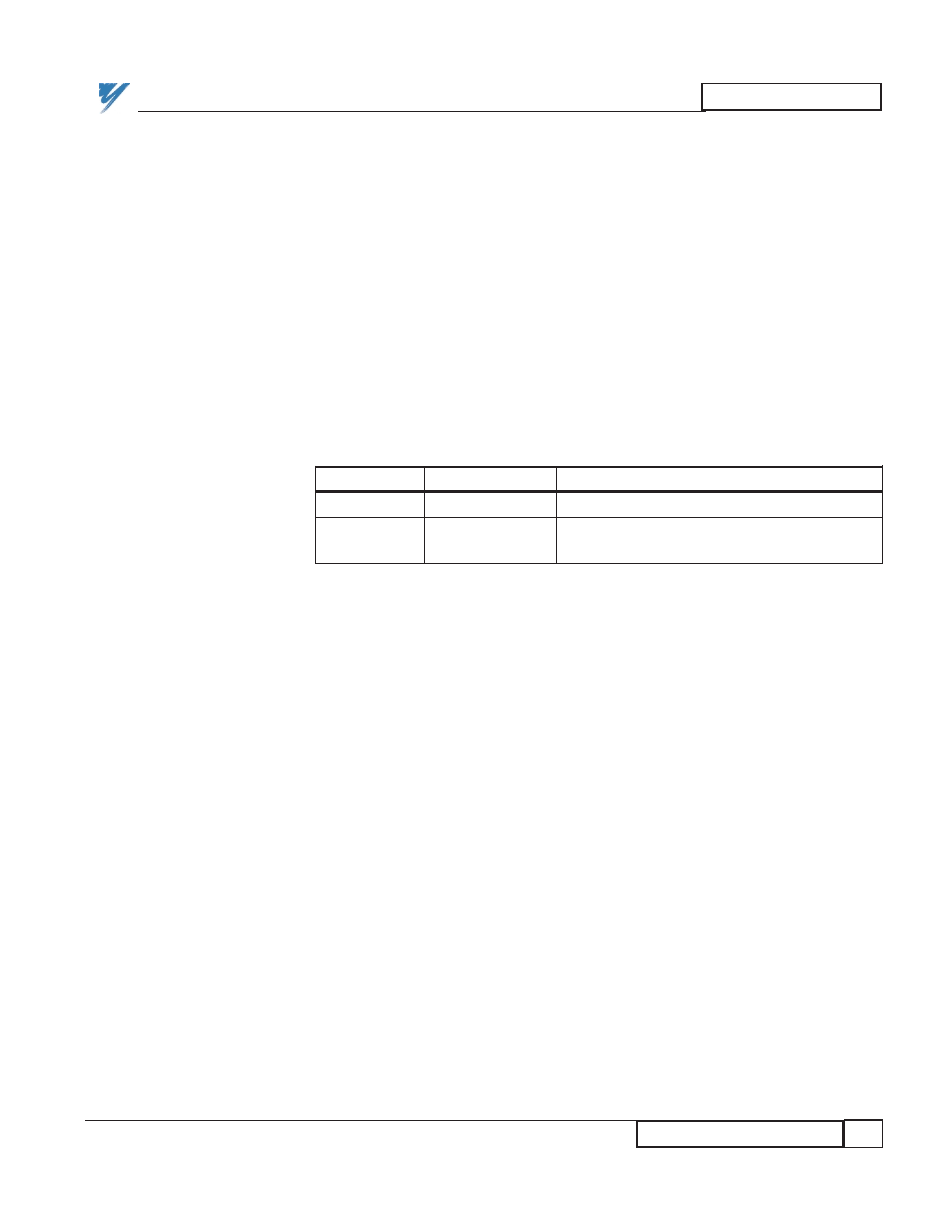
The jumpers located on the JARC board are described in Table 1, with the
defaults shown.
NOTE: On revision "C" and later JARC boards, J1 is an ARCNET
BNC connector and J2 does not exist.
NOTE: If the hand held Portable Command/Display Unit (PCDU)
does not operate properly after plugging into the JARC board J3
RS-232 connector, check the F1 fuse. This fuse protects the +5V
power to the PCDU.
Positions 1 through 8 of DIP switch SW1 determine the LAN node address.
Usually this address is set for 200, when the system has only one PLC gateway.
The address of the second PLC gateway is typically set to 201. Enter the node
ID in binary notation, choosing either a "0" or a"1" for each bit. The least
significant bit is position 1, and the most significant bit is position 8. The
standard gateway addresses are listed in Table 2. The JARC board switches use
pull-down logic, so a closed switch is a logic 0.
JARC Board
Setup
JARC Board
DIP Switch
JARC Board
Jumper
Selections
Table 1. JARC Jumper Selection
JUMPER
DEFAULT
DESCRIPTION
J8
Center - GND
1-2 CTS (Clear to Send for RS-232)
J9
128K - Center
1-2 RAM_CE2 (Internal selection for
128k static RAM chip)