Yaskawa PLC-5 User Manual
Page 9
HARDWARE
6
SmartMUX Board Setup
12/22/94- RD 3196-10
SmartMUX
Board Setup
SmartMUX
Board Baud
Rate / Last
State
The SmartMUX board resides on top of the JARC board and is screwed in
place. The SmartMUX board requires four screws to attach it to the JARC
board.
There are two jumper positions on the SmartMUX board, labeled J1 and J2.
These jumpers are used for EPROM functions which are not required by this
implementation of the SmartMUX board, so these jumpers are not installed.
The SmartMUX board has two 6-position DIP switches, labeled SW1 and
SW2, to select the rack address and baud rate. The rack address must be
consecutive between zero and seven (inclusive), and must match the rack
address set on the JARC board.
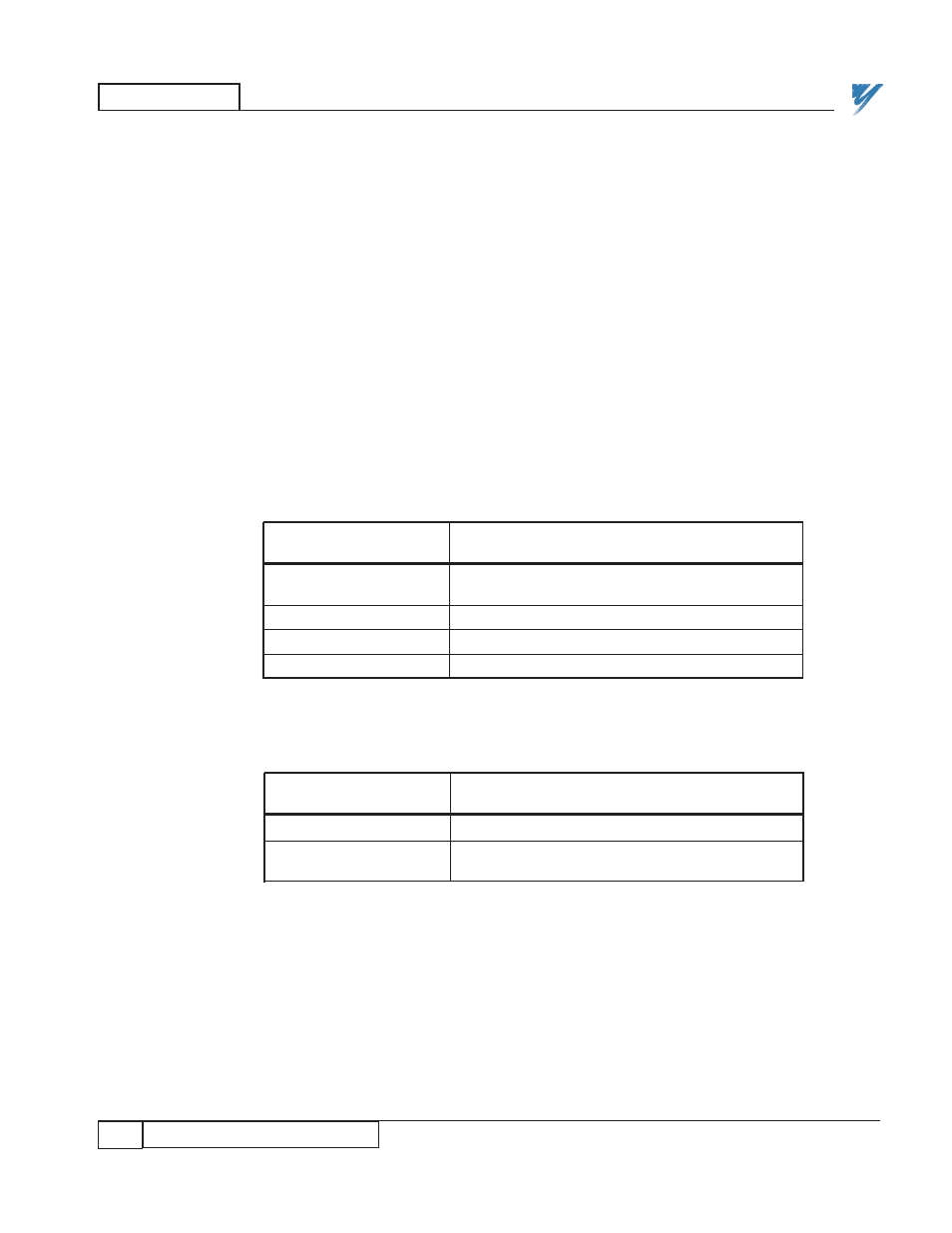
The first DIP switch, SW1, controls the baud rate, last I/O group, last state,
and watchdog (see Tables 6-9), and one bit of the rack address. The "Baud
Rate" and "Last State" should be the only switches that require modification.
Table 6. SmartMUX Board Baud Rate Switch
DIP Switch SW1
BAUD RATE
Position 1
Position 2
57.6K
X
X
(DEFAULT)
115.2K
O
X
230.4K
X
O
230.4K
O
O
X = Closed switch = Switch ON
O = Open switch = Switch OFF
Table 7. SmartMUX Board Last I/O Group Switch
DIP Switch SW1
LAST I/O GROUP
Position 3
NOT LAST
X
LAST
O
(DEFAULT)
X = Closed switch = Switch ON
O = Open switch = Switch OFF