Jarc board led operation – Yaskawa PLC-5 User Manual
Page 8
HARDWARE
5
12/22/94- RD 3196-10
JARC Board LED Operation
Position 12 of DIP switch SW1 enables or disables the hardware watchdog (see
Table 4). The hardware watchdog resets the JARC board if a hardware or
software failure occurs. This feature should be enabled for all installations.
There are four LEDs on the JARC interface board; one power LED and three
user indication LEDs. The placement of the LEDs is shown in Figure 1.
Table 4. JARC Board SW1 DIP Switch, Position 12
WATCHDOG
Position 12
DESCRIPTION
ON
O
Enable Watchdog (DEFAULT)
OFF
X
Disable Watchdog
X = Closed = Logical 0 = Switch ON
O = Open = Logical 1 = Switch OFF
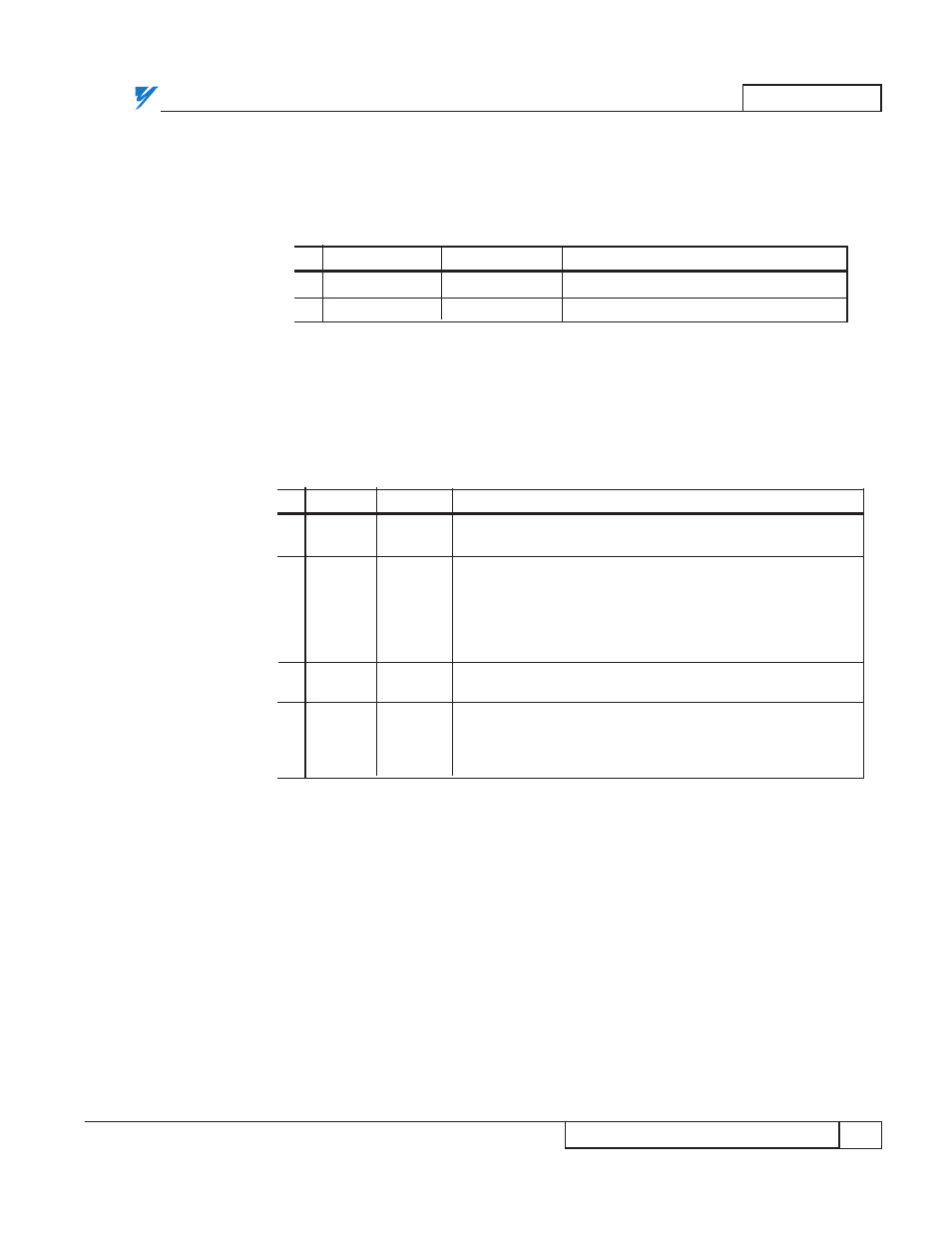
Table 5. JARC Board LED Operation
LED
COLOR
DESCRIPTION
PWR
RED
ON when the JARC board has proper +5V power from the
power supply. The power LED should always be ON.
RECON
YELLOW
ON when a LAN reconfiguration occurs. Each time a node
enters or leaves the network, a reconfiguration occurs. If the
reconfiguration completes and the network is stable, the
RECON LED will turn OFF after about 1-2 seconds. If this
LED is ON constantly or blinks frequently, a network problem
is likely.
XMIT
RED
ON when the JARC board is communicating on the network.
This LED is normally on all the time.
PGM
RED
The PGM LED is used to indicate hardware error conditions.
If this LED is ON, turn off the power to the PLC gateway and
then turn the power back on. If this LED remains ON, then a
hardware problem has been detected with the JARC board.
JARC Board
LED Operation