Hardware – Yaskawa PLC-5 User Manual
Page 7
HARDWARE
4
12/22/94- RD 3196-10
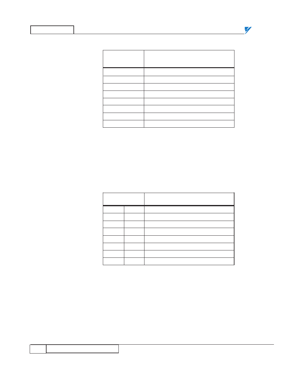
JARC Board DIP Switch
Positions 9, 10, and 11 of DIP switch SW1 determine the starting rack number
for the JARC board to accept on the network (see Table 3). This rack number
must match the lowest rack number selected on the SmartMUX board. The
SmartMUX board is usually wired to JARC board connector J5. Rack 0 is only
valid for a PLC-3.
Table 2. JARC Board SW1 DIP Switch, Positions 1-8
MICROTRAC
SW1 DIP Switch Position
LAN
LSB
MSB
ADDRESS
1 2 3 4 5 6 7 8
200
X X X O X X O O
201
O X X O X X O O
202
X O
X O
X X O O
203
O O X O
X X O O
204
X X O O
X X O O
205
O X O O
X X O O
206
X O O O
X X O O
207
O O O O
X X O O
X = Closed = Logical 0 = Switch ON
O = Open = Logical 1 = Switch OFF
Table 3. JARC Board SW1 DIP Switch, Positions 9 - 11
RACK
SW1 DIP Switch Position
J5 J6
9
10
11
0 1
X
X
X
1 2
O
X
X
2 3
X
O
X
3 4
O
O
X
4 5
X
X
O
5 6
O
X
O
6 7
X
O
O
7 N/A
O
O
O
X = Closed = Logical 0 = Switch ON
O = Open = Logical 1 = Switch OFF