Yaskawa PLC-5 User Manual
Page 15
GENERAL OPERATION
12
PLC to MicroTrac
12/22/94- RD 3196-10
PLC to
MicroTrac
(LOGI)
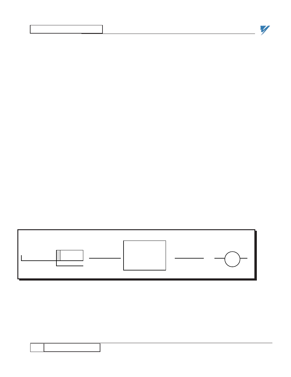
Logic inputs to a PAC schematic from a PLC can be visualized as shown in
Figure 5. Logic input (LOGI) PAC blocks receive a logic value sent to the
drive from the remote device specified by the node, channel, and sub channel
defined for that block. The node number for a single PLC gateway is typically
200. These logics utilize groups 1-7 for a maximum of 112 (7 x 16) PLC to
MicroTrac logic bits.
The channel number is in octal notation. The first digit is a 0, and can be
associated with the A-B PLC output "O" notation. The 2nd and 3rd digits
represent the rack number and the group number. Thus:
LAN CHANNEL 015 = OUTPUT RACK 1, GROUP 5 or O:15
The sub channel number will also be in octal, and will directly correspond to
the bit number of the simulated input. Thus, the 16 possible bits are:
LAN SUB CHANNEL 00 = BIT 00
: :
:
LAN SUB CHANNEL 07 = BIT 07
LAN SUB CHANNEL 10 = BIT 10
: :
:
LAN SUB CHANNEL 17 = BIT 17
Any drive can request logic inputs from any rack and group of the PLC that
has outputs defined for that location. The Drive Kernel software will select the
appropriate bit and send it to the appropriate LOGI block.
NOTE: LAN traffic throughput may significantly improved if all logic
values for a particular drive are grouped together and not needlessly
divided between multiple PLC groups.
Figure 5. PAC Logic Input from PLC
TYPICAL LOGI
101-D
LOGI
Node Chan. Sub
200 015 2
LAN Cable
Logic Bit
PLC Gateway
Remote
I/O Cable
PLC Ladder
Logic
O:015/02