15 explanation of i/o signals, 15 exp, 15 explanation of i/o signals e-40 – Yaskawa Junma Series SERVOPACK User Manual
Page 41: I/o signal timing examples
3.15 Explanation of I/O Signals
E-40
3.15 Explanation of I/O Signals
Pulse train references are given to control the position of the servomotor. The following pulse train output forms are
supported from the host controller.
• Line driver output
• +24-V open-collector output
• +12-V open-collector output
• +5-V open-collector output
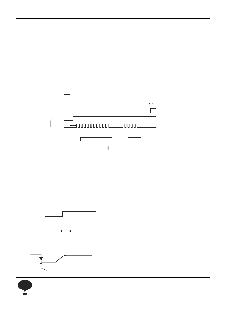
I/O Signal Timing Examples
* 1. The interval from when the servo ON signal is turned ON until the reference pulse is input
must be at least 40 ms, or the reference pulse may not be received by the SERVOPACK. If a
motor with a brake is in used, more time will be required to release the brake. Therefore,
provide an interval of at least 100 ms.
* 2. The error counter clear signal must be ON for at least 20
μs. The clear signal clears the error
counter of the SERVOPACK when the signal is turned from OFF to ON. If the reference pulse
is stops when the clear signal is turned ON, the motor will also stop at that position.
* 3. The lag time for the brake is 100 ms. Use a relay for brakes with an operating time of 30 ms or
less.
Note: 1. The maximum lag time from the time that the error or fault is detected until the time that
the alarm signal is turned ON is 2 ms.
2. If using the phase-C output signal, use an edge exactly when the signal changes from
OFF to ON. Because the wave curve is gentle, the timing to start the next sequence might
vary if not specified.
Failures caused by incorrect wiring or wrong voltage application in the brake circuit may damage
the equipment or cause an accident resulting in death or injury.
Follow the procedures and instructions for wiring and trial operation precisely as described in this
manual.
Servo ON (/S-ON)
Positioning completed (/COIN)
Clear (CLR)
Motor ON
Brake (/BK)
Sign + pulse train
Motor ON
Brake released
L
H
H
ON
ON
ON
t4
t3
t2
t1
(SIGN)
(PULS)
t1: Approx. 40 ms
t2: Approx. 130 ms
*
3
t3
≥ 40 ms
*
1
(Motor with brake: 100 ms)
t4
≥ 20 μs
*
2
2ms max.
Alarm detection
ALM
PCO
An edge from OFF to ON
NOTE