6 electrical installation – Yaskawa AC Drive-Option BRAKING UNIT-CDBR Spec.D User Manual
Page 45
6 Electrical Installation
YASKAWA ELECTRIC TOBP C720600 01C 1000-Series Option CDBR-D, LKEB- Installation Manual
45
■
Wiring Procedure
WARNING! Fire Hazard. Tighten terminal screws to the specified tightening torque. Loose electrical
connections could result in death or serious injury by fire due to overheating. Tightening screws beyond the
specified tightening torque may cause erroneous operation, damage the terminal block, or cause a fire.
Refer to
Wire Gauge and Torque Specifications on page 51
for details.
1.
For all CDBR wiring refer to
for wire gauge and torque specifications and
for the drive and option connection diagram
2.
Connect ground wiring to the ground terminals. Refer to
for descriptions of
CDBR Braking Unit Main Circuit Terminals.
3.
Connect main circuit wires to the main circuit terminals B1, B2, and . Refer to
for descriptions of CDBR Braking Unit Main Circuit Terminals.
4.
Connect control circuit wiring to the control circuit terminals. Refer to
for
details on CDBR braking unit control circuit terminals.
5.
Ensure all main circuit and control circuit wires exit through the openings in the
bottom of the CDBR Braking Unit enclosure.
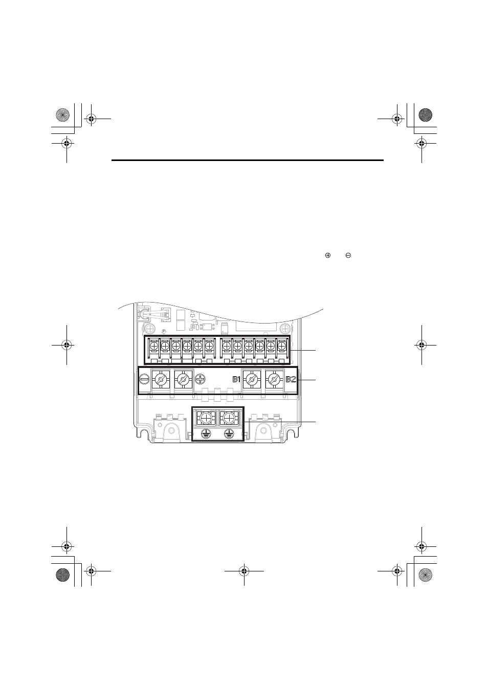
Figure 17
Figure 17 Wiring the Terminals
6.
Reattach the bottom and front cover. After wiring to the CDBR Braking Unit and
drive is complete, double-check all connections before reattaching covers.
EC
EB
EA
MC
MB
MA
SC
SB
OUT2
OUT1
IN2
IN1
Control circuit terminals
Main circuit terminals
Ground terminals
TOBP_C720600_01C_3_0_E.fm 45 ページ 2013年10月7日 月曜日 午後2時20分