Setting the cdbr braking unit, 7 setting and confirming cdbr braking unit, Operation – Yaskawa AC Drive-Option BRAKING UNIT-CDBR Spec.D User Manual
Page 54
54
YASKAWA ELECTRIC TOBP C720600 01C 1000-Series Option CDBR-D, LKEB- Installation Manual
7 Setting and Confirming CDBR Braking Unit Operation
7
Setting and Confirming CDBR Braking Unit Operation
◆
Setting the CDBR Braking Unit
After completing drive and CDBR Braking Unit wiring, confirm the setting of the CDBR
Braking Unit onboard switches.
WARNING! Electrical Shock Hazard. Do not remove covers or touch the circuit boards while the power is
on. Failure to comply could result in death or serious injury.
CAUTION! Burn Hazard. Do not touch a hot heatsink. Failure to comply could result in minor or moderate
injury. To prevent burns, wait at least 15 minutes after power off and ensure the heatsink has cooled down.
■
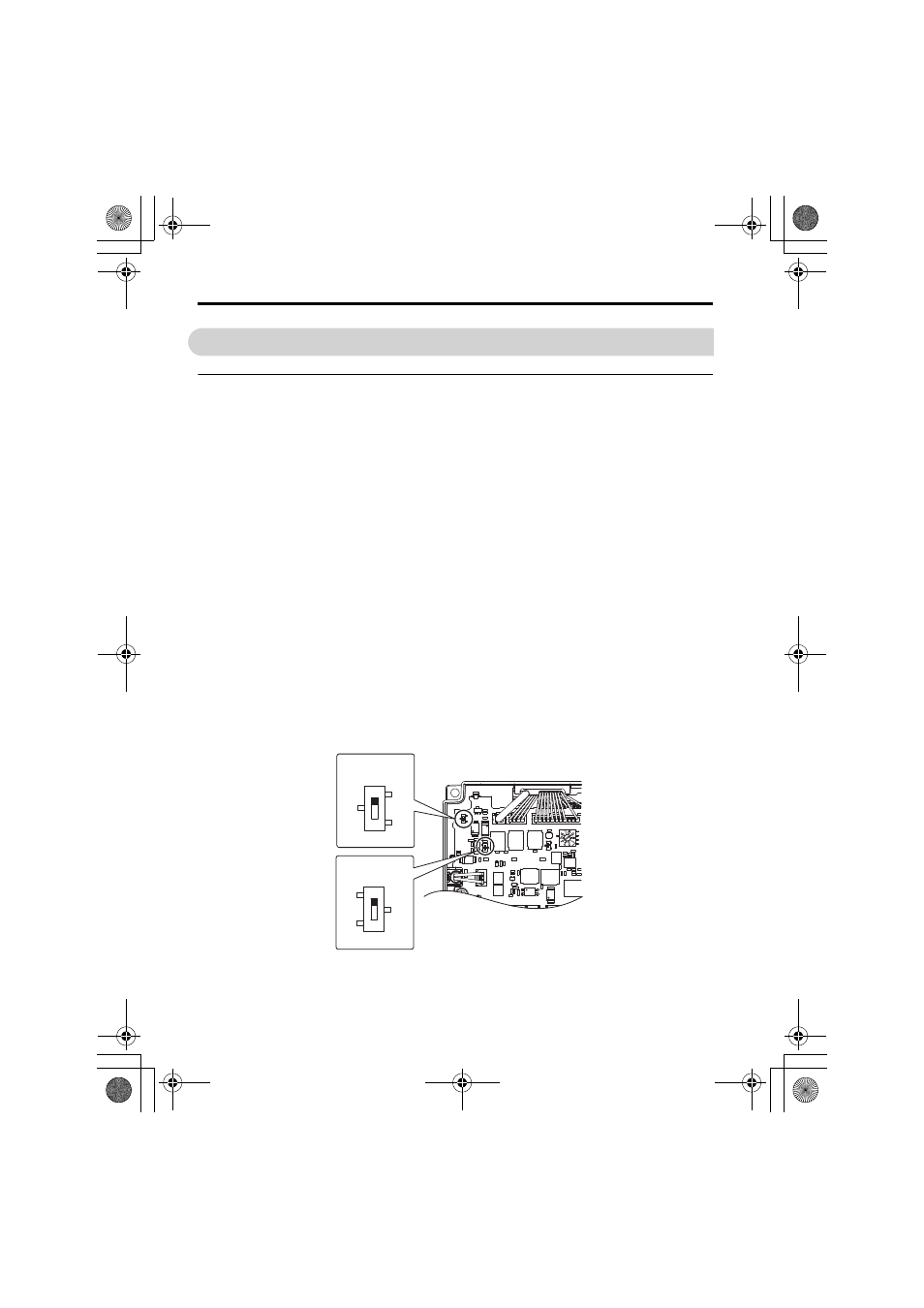
Braking Unit Enable Input Setting (S1, S4, S5 DIP Switch)
The braking unit set to the default setting will turn on only if SB-SC Enable Input is applied.
DIP switch S1 is used to select SINK or SOURE mode for the SB-SC Enable Input. An
external 24 Vdc (Class 2) power supply is required for SOURCE mode.
DIP switch S4 is used to select the contact type N.O or N.C, that will activate the SB-SC
Enable Input.
DIP switch S5 is used to enable or disable the Fault Contact Output MA-MB-MC when
SB-SC Enable Input is activated.
DIP switch default settings:
S1 = SINK Mode
S4 = N.O., setting A
S5 = Enable, setting 2
Note: DIP switch S5 is available from Rev. B or later.
Figure 23
Figure 23 Setting CDBR Onboard DIP Switches
SINK (default)
SOURCE
A (N.O. default)
B (N.C.)
S1 DIP Switch
S4 DIP Switch
TOBP_C720600_01C_3_0_E.fm 54 ページ 2013年10月9日 水曜日 午前9時21分