Yaskawa AC Drive-Option BRAKING UNIT-CDBR Spec.D User Manual
Page 67
9 CDBR Braking Unit and LKEB Braking Resistor Selection
YASKAWA ELECTRIC TOBP C720600 01C 1000-Series Option CDBR-D, LKEB- Installation Manual
67
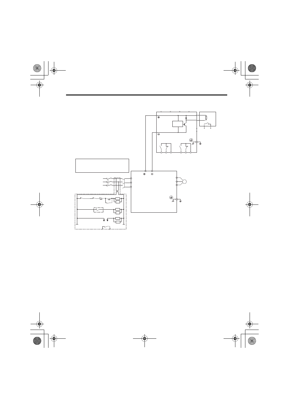
Figure 30
Figure 30 Fault Circuit Connection Diagram B (CDBR Braking Unit)
<1> 200 V class drives do not require a control circuit transformer.
<2> Set L3-04 to 0 or 3 to disable Stall Prevention during deceleration when using an LKEB Braking Resistor Unit.
The motor may not stop within the deceleration time if this setting is not changed.
SC
SB
<2>
B
1
2
P
B1
B2
ELCB (MCCB)
R
T
S
MC
R/L
1
S/L
2
T/L
3
3
M
U/T
1
V/T
2
W/T
3
ON
OFF
THRX
SA
1
2
TRX
MC MA
MC
TRX
MC
SA
SA
THRX
MC
MB
<1>
IN1
IN2
OUT1 OUT2
(Ground)
(Ground)
Drive
Wiring sequence should shut off power to the
drive when a CDBR transistor short-circuit
detection output is triggered or a braking resistor
unit overheat switch is triggered.
Fault relay contact
Braking resistor
overheat switch
(thermal relay trip)
CDBR Braking Unit
LKEB Braking
Resistor Unit
Braking resistor
overheat switch
(thermal relay trip)
Level
sensor
3-phase
CDBR transistor
short-circuit
detection output
250 Vac, max.1 A
30 Vdc, max.1 A
min.5 Vdc, 10 mA
(to customer circuit)
Fault output
250 Vac, max.1 A
30 Vdc, max.1 A
min.5 Vdc, 10 mA
(to customer circuit)
MA MB MC
EA EB EC
TOBP_C720600_01C_3_0_E.fm 67 ページ 2013年11月1日 金曜日 午後2時50分