Refer to, Figure 21, 6 electrical installation – Yaskawa AC Drive-Option BRAKING UNIT-CDBR Spec.D User Manual
Page 48: Connection diagram
6 Electrical Installation
48
YASKAWA ELECTRIC TOBP C720600 01C 1000-Series Option CDBR-D, LKEB- Installation Manual
■
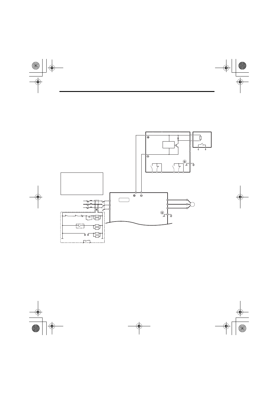
Connection Diagram
WARNING! Fire Hazard. To prevent electrical fire, follow the connection diagrams. Failure to comply may
result in serious injury or death.
Figure 21
Figure 21 Connection Diagram
<1> Set L8-55 to 0 to disable the protection function for the internal braking transistor when using a regenerative unit
or another type of dynamic braking option in lieu of the internal braking transistor. If the protection function is
enabled under these conditions, it may cause a braking resistor fault (rF). This is not available for Varispeed
G7-series.
<2> Set L3-04 to 0 to disable Stall Prevention when using a regenerative converter, a regenerative unit, or a dynamic
braking option. If the function is enabled under these conditions, the drive may not stop within the specified
deceleration time.
<3> Set L8-01 to 1 to enable braking resistor overload protection in the drive when using ERF-type resistors.
<4> Be sure to protect non-Yaskawa braking resistors by thermal overload relay.
Fault relay contact
Braking resistor
overheat switch
(thermal relay trip)
SA
1
2
TRX
MC MA
TRX
SA
ON
OFF
THRX
MC
MC
SA
THRX
MC
MB
Braking resistor
overheat switch
(thermal relay trip)
<1><2>
<2><3><4>
Level
sensor
LKEB Braking
Resistor Unit
CDBR Braking Unit
B1
P
1
2
B
B2
SC
SB
ELCB (MCCB)
R
T
S
MC
3-phase
R/L
1
S/L
2
T/L
3
Main circuit
Drive
Wiring sequence should shut off
power to the drive when a CDBR
transistor short-circuit detection
output is triggered or a braking
resistor unit overheat switch is
triggered.
3
M
U/T
1
V/T
2
W/T
U
V
W
3
(Ground)
IN1
IN2
OUT1 OUT2
(Ground)
Fault output
250 Vac, max.1 A
30 Vdc, max.1 A
min.5 Vdc, 10 mA
(to customer circuit)
CDBR transistor
short-circuit
detection output
250 Vac, max.1 A
30 Vdc, max.1 A
min.5 Vdc, 10 mA
(to customer circuit)
MA MB MC
EA EB EC
TOBP_C720600_01C_3_0_E.fm 48 ページ 2013年11月1日 金曜日 午後2時49分