Figure 22, 6 electrical installation – Yaskawa AC Drive-Option BRAKING UNIT-CDBR Spec.D User Manual
Page 53
6 Electrical Installation
YASKAWA ELECTRIC TOBP C720600 01C 1000-Series Option CDBR-D, LKEB- Installation Manual
53
Figure 22
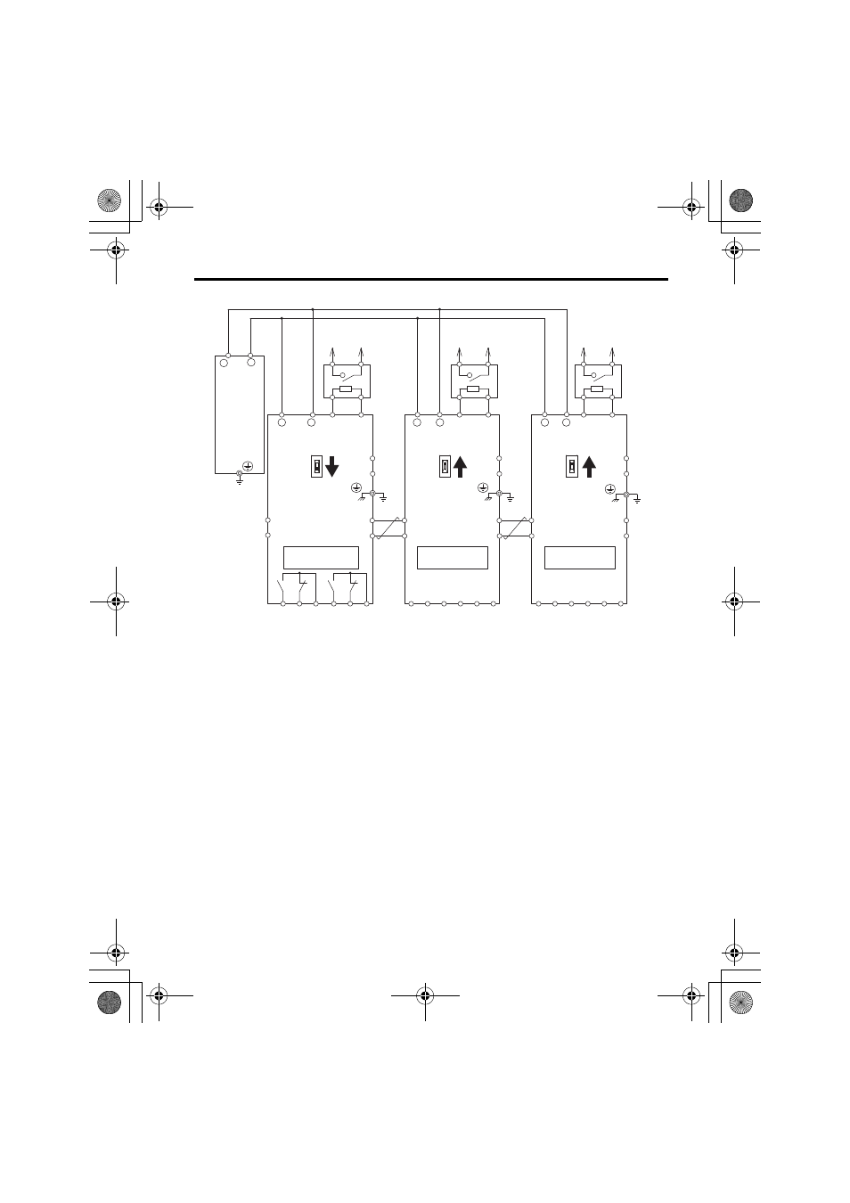
Figure 22 Braking Units in Parallel
Note: Contact your Yaskawa representative or nearest agent when using the CDBR Braking Unit
(CDBR-D) with earlier models (CDBR-, CDBR-B, or CDBR-C).
<1> Connect directly to the drive or install a terminal block.
<2> Connect the thermal relay trip contact to disconnect main input power to the drive.
MA MB MC EA EB EC
MA MB MC EA EB EC
MA MB MC EA EB EC
OUT1
OUT2
SC
SB
SC
SB
SC
SB
OUT1
OUT2
IN1
IN2
IN1
IN2
3
1
P
2
B
−
B1
B2
B
P
B
P
1
2
1
2
+
+
−
B1
B2
OUT1
OUT2
IN1
(Ground)
IN2
B1
B2
+
−
+
−
<1>
<1>
<1>
<2>
<2>
<2>
Drive
Braking resistor
overheat switch
(thermal relay trip)
LKEB
Braking
Resistor
Unit
LKEB
Braking
Resistor
Unit
LKEB
Braking
Resistor
Unit
Braking resistor
overheat switch
(thermal relay trip)
CDBR Braking
Unit 2 (slave)
CDBR Braking
Unit 3 (slave)
CDBR Braking
Unit 1 (master)
IN
(Slave)
OUT
(Master)
IN
(Slave)
OUT
(Master)
IN
(Slave)
OUT
(Master)
Fault output
250 Vac, max.1 A
30 Vdc, max.1 A
min.5 Vdc, 10 mA
(to customer circuit)
CDBR transistor
short-circuit
detection output
250 Vac, max.1 A
30 Vdc, max.1 A
min.5 Vdc, 10 mA
(to customer circuit)
Fault output
250 Vac, max.1 A
30 Vdc, max.1 A
min.5 Vdc, 10 mA
(to customer circuit)
CDBR transistor
short-circuit
detection output
250 Vac, max.1 A
30 Vdc, max.1 A
min.5 Vdc, 10 mA
(to customer circuit)
Fault output
250 Vac, max.1 A
30 Vdc, max.1 A
min.5 Vdc, 10 mA
(to customer circuit)
CDBR transistor
short-circuit
detection output
250 Vac, max.1 A
30 Vdc, max.1 A
min.5 Vdc, 10 mA
(to customer circuit)
Braking resistor
overheat switch
(thermal relay trip)
(Ground)
(Ground)
(Ground)
TOBP_C720600_01C_3_0_E.fm 53 ページ 2013年11月1日 金曜日 午後2時50分