Installation orientation and clearances -12, Installation orientation and clearances, Physical installation 1 - 12 – Yaskawa F7 Drive User Manual User Manual
Page 23
Physical Installation 1 - 12
Installation Orientation and Clearances
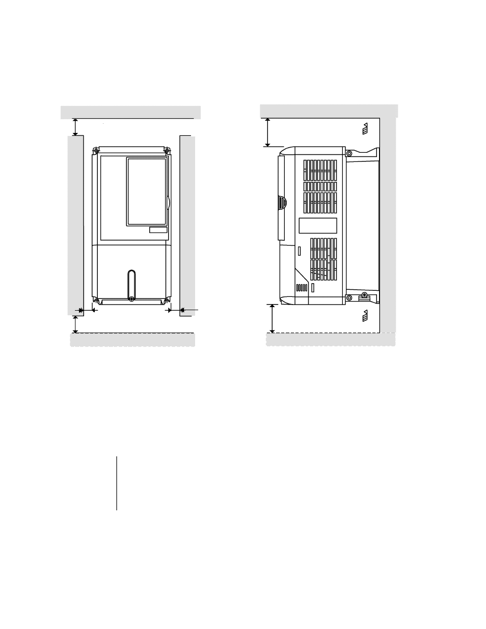
Install the Drive vertically so as not to reduce the cooling efficiency. When installing the Drive, always provide the following
installation clearances to allow normal heat dissipation and air flow. Ensure that the heatsink is against a closed surface to
avoid diverting cooling air around the heatsink.
Fig 1.8 Drive Installation Orientation and Clearance
IMPORTANT
1. The same clearance is required horizontally and vertically for both Open Chassis (IP00)
and NEMA Type 1 Drives.
2. Always remove the top and bottom protection covers before installing a CIMR-F7U2018/
4018 and smaller Drive in a panel.
3. Always provide enough clearance for lifting eye bolts and the main circuit wiring when
installing a CIMR-F7U2022/4030 and larger Drive in a panel.
4.75in *
2
(120mm) minimum
4.75in (120mm) minimum
Air
Air
Vertical Clearance
Horizontal Clearance
1.2in
(30.5mm) minimum
1.2in
(30.5mm) minimum
1.97in (50mm) minimum
1.97in *
1
(50mm) minimum
*
1
For Drive models F7U2110, F7U4160, and F7U4220, this clearance dimension is 4.75in (120mm) minimum.
For Drive model F7U4300, this clearance dimension is 11.8in (300mm) minimum.
All other models require 1.97in (50mm) minimum.
*
2
For Drive model F7U4300, this clearance dimension is 11.8in (300mm) minimum. All other models require 4.75in (120mm) minimum.