Terminal block configuration -2, Terminal block configuration, Electrical installation 2 - 2 – Yaskawa F7 Drive User Manual User Manual
Page 29
Electrical Installation 2 - 2
Terminal Block Configuration
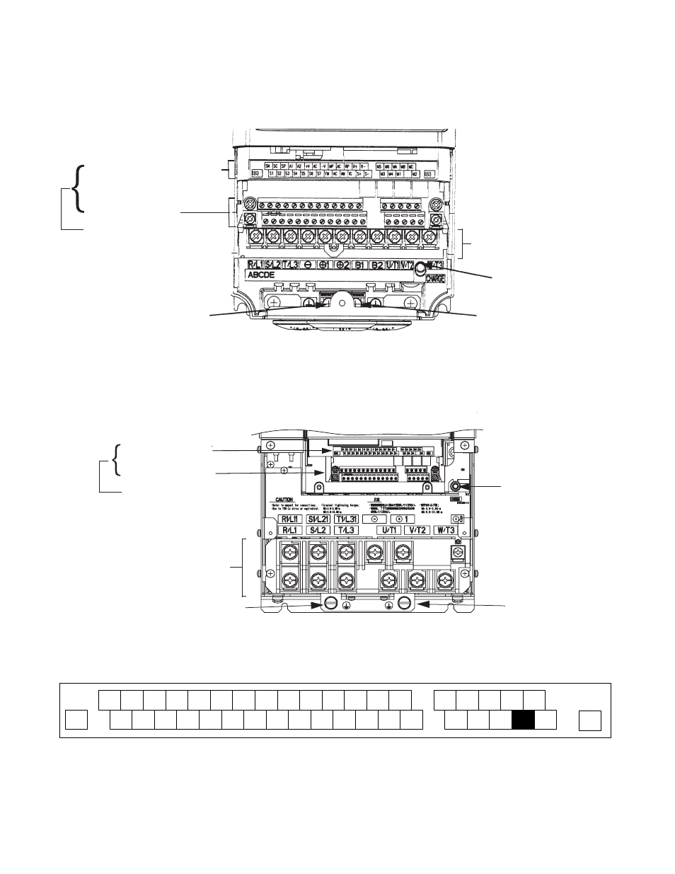
The wiring terminals are shown in Fig 2.1, Fig 2.2 and Fig 2.3.
Fig 2.1 Terminal Configuration for Models CIMR-F7U2018/4018 and Smaller
Fig 2.2 Terminal Configuration for Models CIMR-F7U2022/4022 and Larger
Fig 2.3 Control Circuit Terminal Layout
Ground terminal
Control circuit terminal layout label
Charge indicator
Ground terminal
Main circuit terminals
Ground terminal
Control circuit terminals
See Fig. 2.3 below for
actual terminal layout
Charge indicator
Control circuit terminal
Ground terminal
Main circuit terminals
Ground terminal
layout label
Control circuit terminals
See Fig. 2.3 below for
actual terminal layout
SN
SC
SP
A1
A2
+V
AC
-V
A3
MP
AC
RP
R+
R-
MC
M5
M6
MA MB
S1
S2
S3
S4
S5
S6
S7
S8
FM
AC
AM
IG
S+
S-
M2
M3
M4
M1
E(G)
E(G)