Control wiring -20, Control wiring, Control circuit terminal functions – Yaskawa F7 Drive User Manual User Manual
Page 47: Electrical installation 2 - 20
Electrical Installation 2 - 20
Control Wiring
Control Circuit Terminal Functions
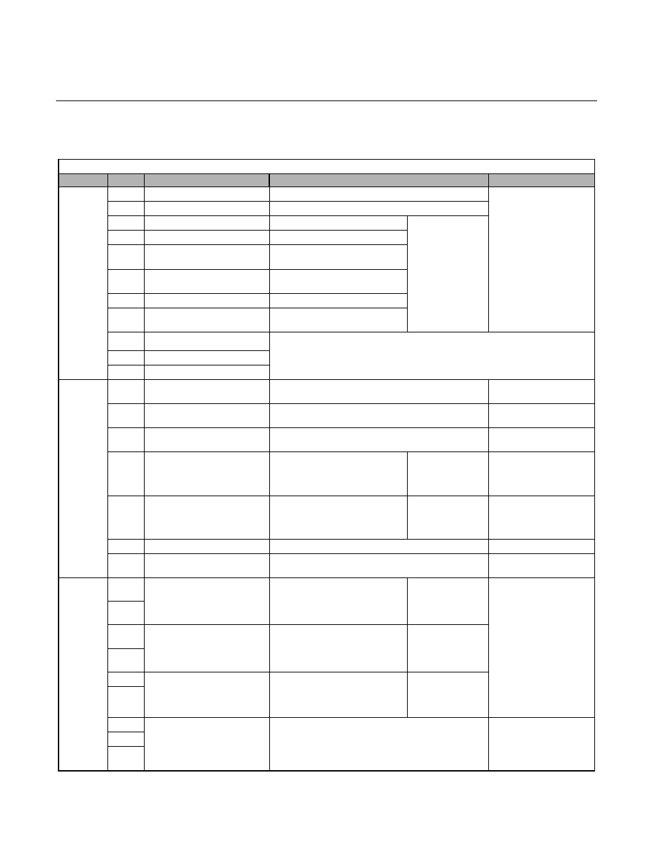
The factory default functions of the control circuit terminals for 2-wire control are shown in Table 2.11.
Table 2.11 Control Circuit Terminals
Type
No.
Default Function
Description
Signal Level
Digital
Input
Signals
S1
Forward run/stop command
Forward run when CLOSED; stopped when OFF.
24Vdc, 8mA
Photocoupler isolation
S2
Reverse run/stop command
Reverse run when CLOSED; stopped when OFF.
S3
External fault input
Fault when CLOSED.
Multi-function
digital inputs.
Functions set by
H1-01 to H1-06.
S4
Fault reset
Reset when CLOSED.
S5
Multi-step speed reference 1
(Master/auxiliary switch)
Auxiliary frequency reference
when CLOSED.
S6
Multi-step speed reference 2
Multi-step setting 2 when
CLOSED.
S7
Jog frequency reference
Jog frequency when CLOSED.
S8
External baseblock N.O.
Shuts off Drive’s output when
CLOSED.
SN
Digital input supply common
Refer to Table 2.15 for connection details.
SC
Digital input photocoupler
SP
Digital input supply +24Vdc
Analog
Input
Signals
+V
+15Vdc power output
+15Vdc power supply for analog inputs or transmitters.
+15Vdc
(Max. current: 20mA)
-V
-15Vdc power output
-15Vdc power supply for analog inputs or transmitters.
-15Vdc
(Max. current: 20mA)
A1
Analog input or
speed command
0 to +10Vdc/100%
0 to +/-10Vdc / 100% (H3-01)
0 to +10V(20k
Ω)
A2
Add to terminal A1
4 to 20mA/100%
0 to +10Vdc / 100% (H3-08)
Multi-function
analog input 2.
Function set by
H3-09.
4 to 20mA(250
Ω)
0 to +/-10V(20k
Ω)
A3
Aux. frequency reference 1
0 to +10Vdc/100%
0 to +/-10Vdc / 100% (H3-04)
Multi-function
analog input 3.
Function set by
H3-05
0 to +/-10V(20k
Ω)
AC
Analog common
–
–
E(G)
Shield wire, optional ground
line connection point
–
–
Digital
Output
Signals
M1
During run
(N.O. contact)
CLOSED during operation.
Multi-function
digital output.
Function set by
H2-01.
Form A
Dry contacts
capacity:
1A max. at 250Vac
1A max. at 30Vdc
M2
M3
Zero Speed
(N.O. contact)
CLOSED when below minimum
frequency.
Multi-function
digital output.
Function set by
H2-02.
M4
M5
Frequency agree
(N.O. contact)
CLOSED when set frequency
matches output frequency.
Multi-function
digital output.
Function set by
H2-03.
M6
MA
Fault output signal
(SPDT)
MA/MC: CLOSED during fault condition
MB/MC: OPEN during fault condition
Form C
Dry contacts
capacity:
1A max. at 250Vac
1A max. at 30Vdc
MB
MC