Communications d - 11 – Yaskawa F7 Drive User Manual User Manual
Page 230
Communications D - 11
Monitor Data
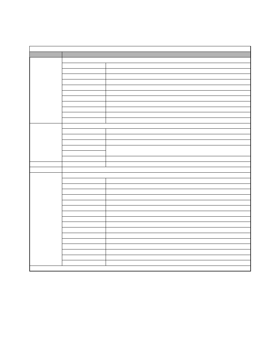
The following table shows the monitor data. Monitor data can only be read.
Table D.5 Monitor Data
Register No.
Contents
0010H
Status signal
Bit 0
Run command
Bit 1
At zero speed
Bit 2
Reverse operation
Bit 3
Fault reset signal
Bit 4
Speed agree
Bit 5
Drive ready
Bit 6
Alarm
Bit 7
Fault
Bits 8 to D
Not used
Bit E
ComRef
Bit F
ComCtrl
0011H
Fault details
Bit 0
OPE error
Bit 1
Err error
Bit 2
Program mode
Bit 3
1CN status
Bit 4
Bit 5 to F
Not used
0012H
oPE details
oPE error code (OPE01=1, OPE02=2, OPE03=3, OPE06=6, OPE10=10, OPE11=11)
0013H
Not used
0014H
Fault content 1
Bit 0
Fuse blown (FU)
Bit 1
DC bus undervoltage (UV1)
Bit 2
Control power supply undervoltage (UV2)
Bit 3
Main circuit answerback (UV3)
Bit 4
Not used
Bit 5
Ground fault (GF)
Bit 6
Overcurrent (OC)
Bit 7
Overvoltage (OV)
Bit 8
Heatsink overtemperature (OH)
Bit 9
Drive overheat (OH1)
Bit A
Motor overload (OL1)
Bit B
Drive overload (OL2)
Bit C
Overtorque 1 (OL3)
Bit D
Overtorque 2 (OL4)
Bit E
Dynamic Braking Transistor (RR)
Bit F
Dynamic Braking Resistor (RH)
Note: Write 0 to all unused bits. Do not write data to reserved or “Not Used” registers and bits.